6-16
176183-1CD
HW1483638
6
Disassembly and Reassembly of Speed Reducer
6.5 Disassembly and Reassembly of B-Axis Speed Reducer
MH5S
(II)
/MH5F
4. Insert the wave generator
in the housing
and press fit the
bearing
.
5. Attach the conical spring washers to the hexagon socket head cap
screws
and mount the housing
on the wrist base.
6. Attach the conical spring washers to the hexagon socket head cap
screws
and mount the whole wrist unit reassembled from the step 1
through 8 on the U-arm. Tighten them with the tightening torque
shown in
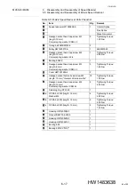
Table 6-5 “B-Axis Speed Reducer Parts Checklist”
.
7. Mount the pulley
on the wave generator
.
8. Apply LOCTITE 242 to the thread part of the hexagon socket head cap
screw
and tighten it with the tightening torque shown in
.
9. Mount the U-arm 2 unit on the U-arm with the GA-SA bolts
-b.
Tighten them with the tightening torque shown in
.
10. Mount the T-axis unit on the U-arm with the GA-SA bolts
-c. Tighten
them with the tightening torque shown in
11. Mount the B- and T-axes motor unit on the U-arm and hang the timing
belt
.
12. Adjust the tension of the timing belt
“Disassembly and Reassembly of B- and T-Axis Timing Belts”
13. Mount the B- and T-axes motor unit with the GA-SA bolts
-a.
Tighten them with the tightening torque shown in
.
14. Mount the cover
with the hexagon socket button head screws
and tighten them with the tightening torque shown in
.
15. Turn ON the DX100/DX200/FS100 power supply.
3
15
19
9
15
4
6
3
7
14
14
5
5
14
10
11
63 of 99


