9-6
168283-1CD
168283-1CD
Hardware Installation &
Software Upgrade
9 Description of Units and Circuit Boards
External Enable Switch (Deadman Switch on Teach Pendant)
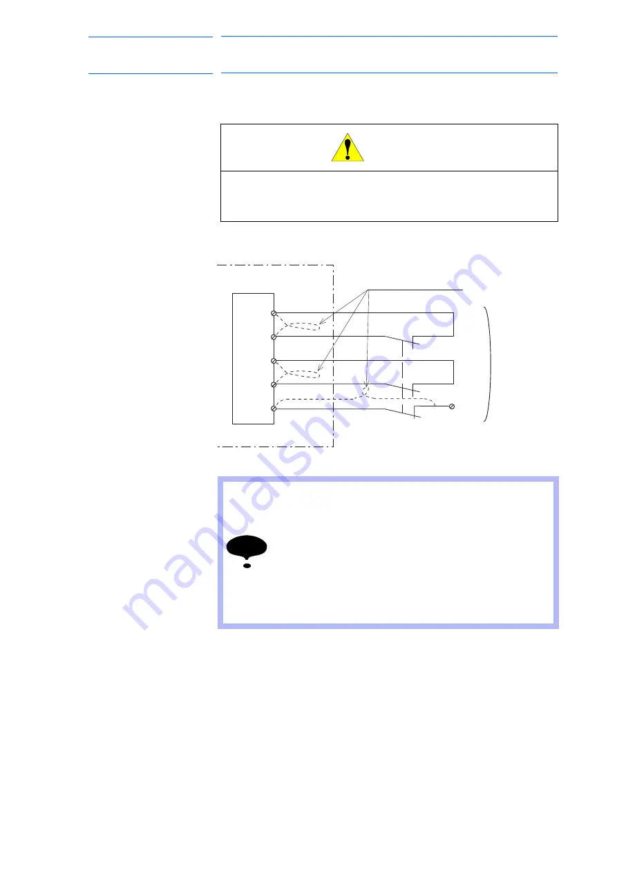
This signal is used to connect an Enable switch such as the one on the
teach pendant or an additional device when two people are teaching.
Fig. 9-3: Connection for External Enable Switch
CAUTION
•
Always connect the signals after removing the jumpers.
Injury or damage to machinery may result because the external
emergency stop do not work even if the signal is input.
NOTE
• If multiple External Enable Switches are present in the
system, all contacts must be wired in series to the TB2-5
status input.
• If a teach pendant is also used, the enabling device(s)
should be wired in series with teach pendant enable
switch.
• Refer to the Pendant Interface Kit drawing, 165143-1, for
wiring of the Fuji Pendant. Refer to
suggested wiring of the Rockwell MobileView teach
pendant.
TB2-10
TB2-13
TB2-17
TB2-20
Guard Device
MLX200
Turn ON/OFF
at the same time
(all 3 contacts)
Remove the jumpers
Robot system safety
input terminal blocks
TB2-5
Enable Switch Status
input (see NOTE)
TB2-2
(0 VDC)
76 of 121


