7-3
173124-1CD
HW1482991
7
System Application
7.2 Internal User I/O Wiring Harness and Air Line
MPL300
II
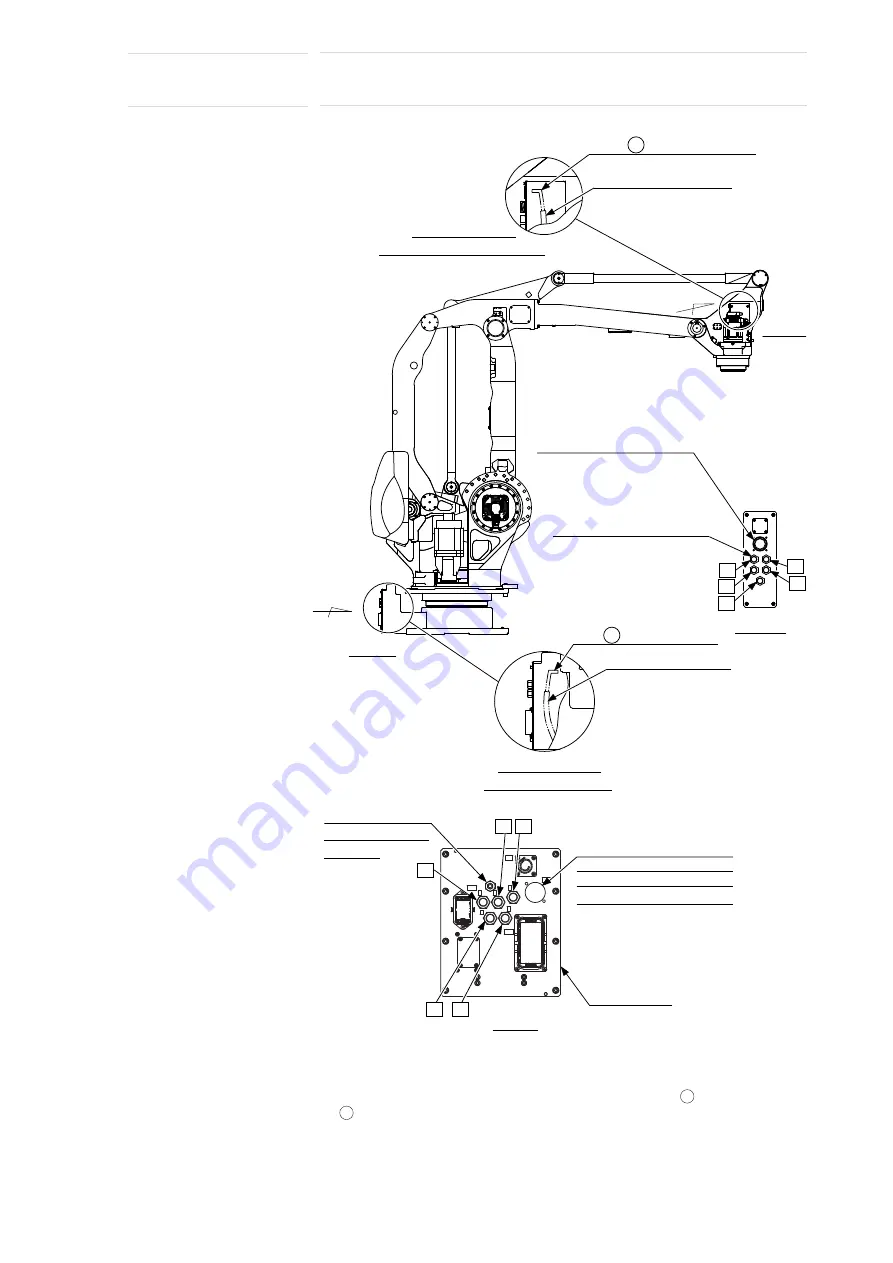
Fig. 7-2(a): Connectors for Internal User I/O Wiring Harness and Air Line
Note 1: This manipulator has a built-in tube for a field bus cable. A cable with a
cross sectional area of 2 mm
2
is provided in the tube in advance. To run a field
bus cable through the manipulator, remove the covers of the connector base
and the junction box, fix the field bus cable with the cable
, and pull the cable
on the wrist.
Note 2: As shown in
Fig. 7-2(b) “Field Bus Cable Connection”
, the tube for a field
bus cable (inside dia.: 12 mm) is connected by a union in the Z part of the S-
head.
Connector for the internal user I/O
wiring harness (base side):
JL05-2A24-28PC (with a cap)
Prepare connector: JL05-6A24-28S
Air inlet: A, B, C, D, E
PT3/8 with a pipe plug
(5 places)
View A
Connector base
E
D
C
B
S1
2BC
1BC
FB
C
D
E
A
B
A
C
B
A
E
D
B
A
View B
Connector for the internal user I/O
wiring harness (wrist side):
JL05-2A24-28SC (with a cap)
Prepare connector: JL05-6A24-28P
Tube for field bus cable
(inside dia.: 12)
Tube for field bus cable
(inside dia.: 12)
Exhaust port: A, B, C, D, E
PT3/8 with a pipe plug (5 places)
Cable B (See "Note 1" below.)
Details of Part Y
(inside the junction box of the wrist)
Part Y
Part X
Cable A (See "Note 1" below.)
Details of Part X
(inside the connector base)
A
B
57 of 100


