10 Maintenance and Inspection
10.2Maintenance for Manipulator
10-9
180788-1CD
HW1484370
MPX2600
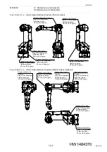
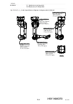
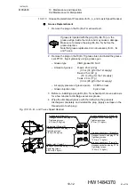
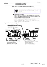
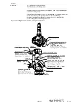
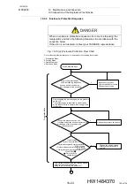
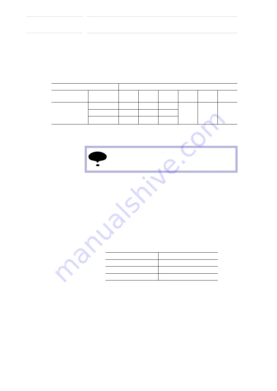
1. Before injecting grease, the posture of the manipulator must be set as
indicated in
Table 10-3 “Recommended Posture for Grease Injection”
If it is difficult to make the recommended posture because of external
cabling or etc., adjust the posture as much as possible to make the
position of grease inlet located in the lower part and the position of
exhaust port located in the upper part. If the exhaust port is located in
the lower part, grease may not be exchanged properly.
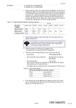
Table 10-3: Recommended Posture for Grease Injection
2. Remove the hexagon socket head plugs from the grease inlet and
grease exhaust port.
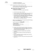
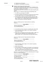
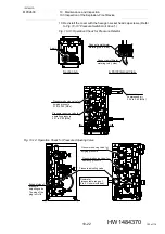
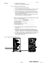
3. Install a grease zerk A-PT3/8 to the grease inlet.
(The grease zerk is delivered with the manipulator.)
4. Inject the grease through the grease inlet using a grease gun.
– Grease type:
VIGO grease RE No.0
– Recommended grease lubricator: Powerlube P3C (made by
Macnaught)
– Amount of grease:
7 g/s or less
(For example, if grease is supplied from the lubricator at 2 times/s,
set the amount to 3.5 g/time or less.)
– Air supply pressure of grease pump: Approximately 0.3 MPa or less
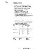
Table 10-4: Amount of Grease
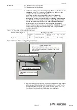
5. The old grease is discharged from the grease exhaust port. At this
time, stop injection when the mixture of the old grease and the new
grease in an equal ratio is seen.
Posture
Mounting
Condition
Axis to inject
S-axis
L-axis
U-axis
R-axis
B-axis
T-axis
Floor-mounted
Wall-mounted
Ceiling-mounted
S-axis
0°
Any
Any
Any Any
Any
L-axis
Any
0°
Any
U-axis
Any
0°
0°
NOTE
The positions of grease inlet and exhaust port are different
depending on the mounting condition of the manipulator.
Confirm the positions beforehand.
Axis to exchange grease Amount of grease
S-axis
Approx.4200 g
L-axis
Approx.2300 g
U-axis
Approx.1650 g
90 of 116


