5-11
167109-1CD
HW1482308
5
Basic Specifications
5.6 Alterable Operating Range
MS165
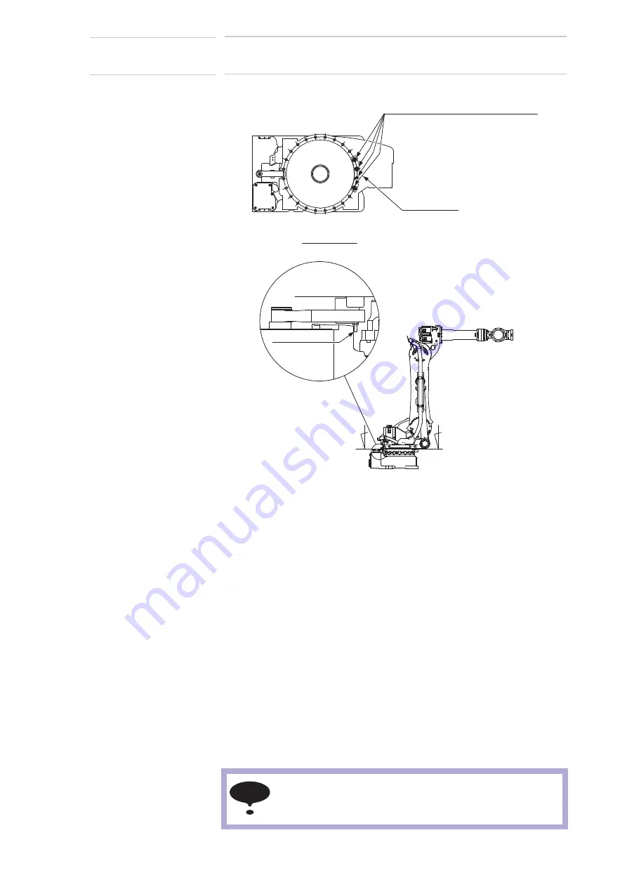
Fig. 5-10: The Components of the S-Axis Stopper
5.6.2 Notes on the Mechanical Stopper Installation
For S-Axis mechanical stopper, install the stopper (drawing No.
HW1405450-1) with the pin which is used bottom up (drawing No.
HW0402104-1) as in
fig. 5-10 “The Components of the S-Axis Stopper”
.
DO NOT forget to apply Locktite 243 to the thread part of the pin before
inserting it into the stopper.
Mount the stopper to the S-head with four hexagon socket head cap
screws M16 (length: 35 mm) and tighten the screws with the tightening
torque of 348 N•m (tensile strength: 1200 N/mm
2
or more). The stopper is
to be installed as shown in the
when the operating range is
±180°.
The stopper can be installed by every 15 degree pitch, however, to avoid
the mechanical troubles caused by interference between stoppers (e.g.
±15°, ±165°), install the S-axis mechanical stopper referring to
table 5-3
“The Settable Angle for S-Axis Stopper”
.
Hexagon socket head cap screws M16
(4 screws)(length: 35)
Conical spring washer 2H-16 (4 washers)
Section A-A
(tensile strength: 1200 N/mm
2
or more)
Stopper
HW1405450-1
Pin
HW0402104-1
A
A
NOTE
1. Apply the specified components when mounting the S-
Axis mechanical stopper.
2. TURN OFF the electric power supply before mounting.
40 of 100


