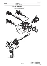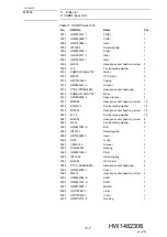
9
Maintenance and Inspection
9.4 Gas Maintenance Procedure in the Gas Balancer
9-18
167109-1CD
HW1482308
MS165
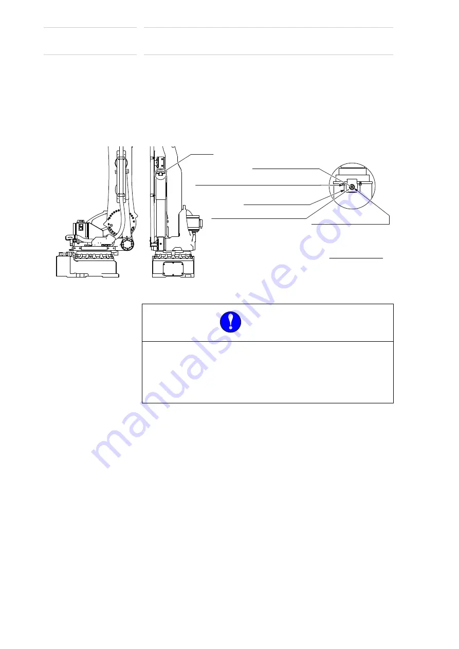
7. Remove the quick connector and mount the cover, then tighten the
hexagon socket head screw plug M6 with flange by using a tightening
torque of 4.9 N•m (0.5 kgf•m).
8. Mount the cover and tighten the hexagon socket head cap screws M4
(length: 6mm) with a tightening torque of 2.8 N•m (0.29 kgf•m.)
9. Turn ON the power supply of the DX200.
Fig. 9-11: Gas in Gas Balancer Pressure Inspection
9.4.3
Gas Discharging Procedure
9.4.3.1 Necessary Devices
Prepare following devices when discharging gas
• Gas filling device: HW1485204
The device includes:
Digital pressure gauge: GC64-173
Quick connector: 10-358-6297
Valve of the service gauge: SS-1KS4
• Thermometer (for measuring the gas balancer surface)
MANDATORY
•
Discharge all gas from the gas balancer when in the following
cases.
– When dismounting the gas balancer from the manipulator.
– When air-flight the gas balancer.
(It is treated as a hazardous material when the gas balancer is
air-flight with gas filled.)
Cover
㸦
HW1405134-1
㸧
㸧
㸦
Surface temperature measuring point
Gas inlet/gas exhaust port
Enlarged figure
A part
Measure on the surface
of the gas balancer
after removing the cover.
Conical spring washer 2L-4 (2 washers)
Hexagon socket head cap screw M4 (length: 6 mm)(2 screws)
A part
Hexagon socket head screw plug M6
with flange
79 of 100


