32
3. Turn OFF the Controller.
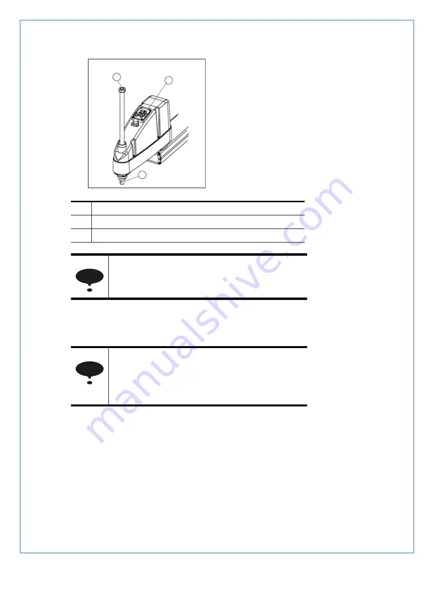
4. Loosen the lower limit mechanical stop set screw (M5 x 6).
5. The upper end of the shaft defines the maximum stroke. Move the lower limit mechanical
stop down by the length you want to limit the stroke.
For example, when the lower limit mechanical stop is set at 150 mm stroke, the lower limit
Z coordinate value is -150. To change the value to “-100”, move the lower limit mechanical
stop down “50 mm”. Use calipers to measure the distance when adjusting the mechanical
stop.
1
Lower limit mechanical stop, 2 screws M5 x 6
2
Brake release button
3
Shaft
When you press the brake release button, the shaft may
lower and rotate due to the weight of the end effector.
Be sure to hold the shaft by hand while pressing the
button
.
A mechanical stop is mounted on both the top and bottom
of Z. However, only the position of the lower limit
mechanical stop on the top can be changed. Do not
remove the upper limit mechanical stop on the bottom
because the calibration point of Z is specified using the
stop.
1
2
3
NOTE
NOTE
Summary of Contents for MOTOMAN MYS450L
Page 26: ...26 E1101000117GB01 MYS450L 5 3 Dimensions 4 5 12 1 200 6 7 8 9 10 3 11 Dimensions mm...
Page 40: ...40 E1101000117GB01 MYS450L 8 Electrical Equipment Specification 8 1 Signal cable BASE ARM2...
Page 41: ...MYS450L E1101000117GB01 41 8 2 Power cable BASE ARM2...
Page 60: ...60 E1101000117GB01 MYS450L...
Page 61: ...MYS450L E1101000117GB01 61...


