8.2 Connection of Signals for Servo Power Supply Individual Control
8-2
8.2
Connection of Signals for Servo Power Supply
Individual Control
The servo power supply individual control function turns ON/OFF the servo power supply in
units of contactor unit. “ON_EN” signal of power supply contactor unit is used.
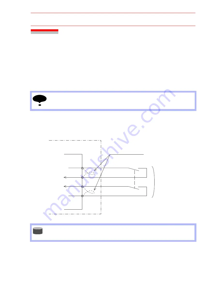
“ON_EN” signals of each power supply contactor unit is connected to the following terminals.
• Power supply contactor unit (JZRCR-NTU
-
): CN06-1 and -2
CN06-3 and -4
Connect the servo power supply individual control signals in the following manner.
1. Remove the jumpers connected to the above mentioned contactor unit terminals.
2. Connect an output contact such as area sensor to “ON_EN” terminal as shown in the
figure below.
For safety reasons, dual circuits are used for the Servo-ON Enable input signals. Connect
the signal so that both input signals are turned ON or OFF at the same time. If only one
signal is turned ON, an alarm occurs.
For the wiring termination and connecting method, refer to “WAGO Connector” in “12.3.2
Units and Circuit Boards in the CPU Unit” of NX100 Instructions.
Short-circuited between the above terminals as a standard.
NOTE
CN06
-1
-2
-3
-4
+24V2
ONEN1
ONEN2
024V
Servo-ON enable input signal
Turn ON/OFF
at the same time
Power supply contactor unit
JZRCR-NTU
Remove the jumper cable
NX100
SUPPLE-
MENT
192/210


