4
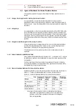
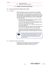
L-Axis Fixing Jig
4.2
Installation and Removal of the L-axis Fixing Jig
4-4
HW1485471
HW1485471
4.2
Installation and Removal of the L-axis Fixing Jig
Refer to
table 4-1 “Parts Check List of L-Axis Fixing Jig”
of Specified Jig Installation”
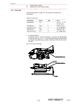
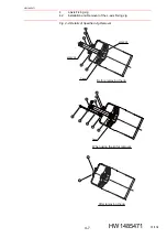
fig. 4-4 “Details of Specified Jig
Installation
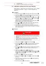
1. Remove the rubber cap
and hexagon socket head cap screws
.
2. Insert the stud
from the thread part M36 into the hole at the rear of
the balancer, and then screw it into the rod
.
Tighten so there is no looseness between the stud
and the rod
.
3. Mount the nut
on the stud
. Screw the nut
onto the stud
until it makes contact with the rear of the balancer.
Tighten so there is no looseness between the end face of the nut
and the contact surface of the rear of the balancer.
4. Mount the shaft
, and then tighten the hexagon socket head cap
screws
with the tightening torque shown in
.
5. Confirm that the L-axis is firmly fixed by releasing the L-axis motor
brake. (Release the brake in short intervals and prepare for the impact
when the arm moves.)
Removal
1. Remove the shaft
and nut
attached to the stud
.
2. Mount the plate
to the stud
by using the hexagon socket head
cap screw
, and tighten it with the tightening torque shown in
.
3. Mount the plate
to the case by using the hexagon socket head cap
screws
, and tighten them with the tightening torque shown in
.
4. Tighten the bolts
until the nut
becomes loose.
If the nut is tight, mount the hexagon nuts
on the tip of the bolts
,
and then screw in the bolts
so that they push the plate
until the
nut
can be moved by hand.
5. Remove the stud
from the rear of the balancer.
6. Remove the plate
, plate
, and bolts
mounted to the stud
and case.
7. Tighten the hexagon socket head cap screws
with the tightening
torque shown in
8. Mount the rubber cap
on the balancer.
1
2
3
4
3
4
5
3
5
3
5
6
7
DANGER
•
To remove the L-axis fixing jig, first confirm that the L-axis holding
power has been restored (that the brake of the L-axis motor has not
released).
Failure to observe this leads unexpected L-arm rotation at the
moment when the L-axis fixing jig is removed and it may result in
damage to machinery, death, or serious injury.
6
5
3
8
3
9
10
11
12
5
13
12
12
10
5
3
8
10
12
3
2
1
28/134


