4
L-Axis Fixing Jig
4.3
Mechanism
4-8
HW1485471
HW1485471
4.3
Mechanism
• Refer to
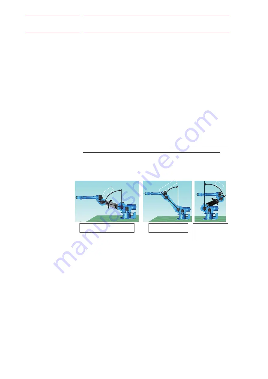
fig. 4-5 “The L-arm Rotation Direction”
The L-arm rotational direction of when L-axis holding power is released
depends on the extent of the torque Tb generated by the balancer, and the
load torque TL generated around the L-axis.
When no load is applied to the edge, the torque Tb generated by the
balancer is always generated toward the direction which makes the L-arm
posture lean 40
°
forward from the vertical posture, and the extent of the
torque Tb varies depending on the L-axis angle. Also, the load torque TL
which is generated around the L-axis works around the center of the L-
axis rotation, and its direction and extent vary depending on the edge
load, posture of the wrist, the U-arm, and the L-arm.
When no load is applied to the edge, for the L-arm rotational direction, 3
patterns are assumed as described in
.
It is quite difficult to accurately compare the extent of the torque which
works around the L-axis and the extent of the torque which is generated
by the balancer on the actual work site, and also, the rotational direction
cannot be identified in this unit. Therefore, handling this unit in the same
way as other manipulators is seriously dangerous, as the L-arm may
rotate in an unexpected direction.
Fig. 4-5: The L-arm Rotation Direction
Posture in which L-arm moves
in the clockwise direction
Posture in which
L-arm doesn’t move
Posture in which
L-arm moves in
the counterclockwise
direction
75
45
to 55
60
32/134

