5
Notes on Grease Replenishment/Exchange Procedures
5.1
Grease Exchange Procedures for Each Axis Speed Reducer
5-7
HW1485471
HW1485471
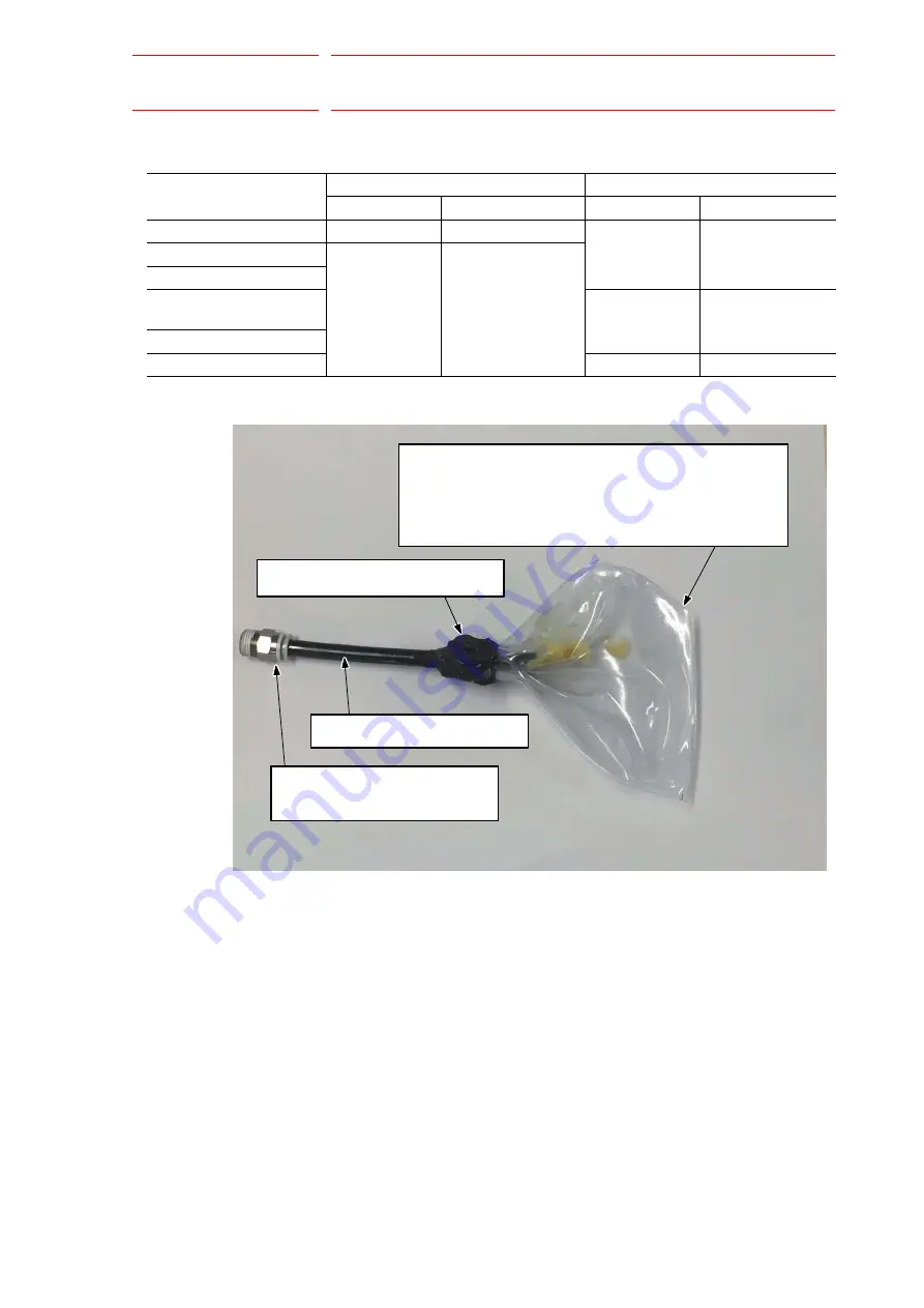
Fig. 5-2: Grease Receiving Bag (Example)
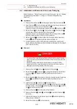
10. Wipe the discharged grease with a cloth, and reinstall the plug. Clean
and degrease the tap part and the thread part of the plug. Wrap the
seal tape TB4501 around the plug, attach it to the grease exhaust port,
and then tighten the plug with the tightening toque shown in
“Plug Type and Tightening Torque for Each Axis”
.
Table 5-6: Plug Type and Tightening Torque for Each Axis
Axis to exchange grease
Plug for the grease inlet
Plug for the grease exhaust port
Plug type
Tightening torque
Plug type
Tightening torque
S-axis
PT1/4
12 N•m (1.2 kgf•m)
PT3/8
23 N•m (2.34 kgf•m)
L-axis
PT1/8
4.9 N•m (0.5 kgf•m)
U-axis
In the casing
R-, B-, and T-axis gear
PT1/8
4.9 N•m (0.5 kgf•m)
R-, and B-axes
T-axis
PT1/16
3.9 N•m (0.4 kgf•m)
Tube (inside dia.: 6 mm or more)
Grease receiving bag
Bond for fixing a grease receiving bag
Union (inside dia.: 6 mm or more)
PT3/8
Cut one corner to remove air.
To prevent grease from scattering from the cut corner,
cover the receiving bag with a plastic bag etc. without
being sealed.
39/134


