5
Notes on Grease Replenishment/Exchange Procedures
5.1
Grease Exchange Procedures for Each Axis Speed Reducer
5-8
HW1485471
HW1485471
5.1.3 Grease Replenishment for Balancer Link Part
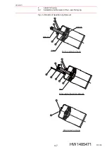
Fig. 5-3: Balancer Link Part
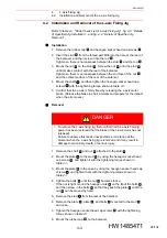
1. Remove the plugs from the grease inlet and from the air exhaust port
of the link
and
. (Refer to
2. Inject grease through the grease inlet of the link
and
using a
grease gun.
– Grease type:
Alvania EP Grease 2
– Amount of grease:
to the link
: 4.35 g (5 cc)
(8.7 g (10 cc) for 1st supply)
to the link
: 4.35 g (5 cc)
(8.7 g (10 cc) for 1st supply)
3. Reinstall the plug to the air bleed port of the link
,
, and
.
Before installing the plug, clean and degrease the thread part of the
plug. Wrap the seal tape TB4501 around the thread part, and then
tighten the plug with a tightening torque of 4.9 N•m (0.5 kgf•m).
4. Reinstall the plug to the grease inlet of the link
,
, and
.
Before installing the plug, clean and degrease the thread part of the
plug. Wrap the seal tape TB4501 around the thread part, and then
tighten the plug with a tightening torque of 4.9 N•m (0.5 kgf•m).
(Hexagon socket head
plug PT1/8)
(Hexagon socket head
plug PT1/8)
(Hexagon socket head plug PT1/8)
(Hexagon socket head plug PT1/8)
(Hexagon socket head plug PT1/8)
(Hexagon socket head plug PT1/8)
Link air exhaust port
3
Link grease inlet
3
Link air exhaust port
2
Link grease inlet
2
Link air exhaust port
1
Link grease inlet
1
NOTE
Grease will not flow out of the air bleed port.
Be careful not to inject too much grease.
1
2
1
2
1
2
1
2
3
1
2
3
40/134


