6
Disassembly and Reassembly of the Motors
6.4
Disassembly and Reassembly of the R-, B-, T-Axis Motors
6-20
HW1485471
HW1485471
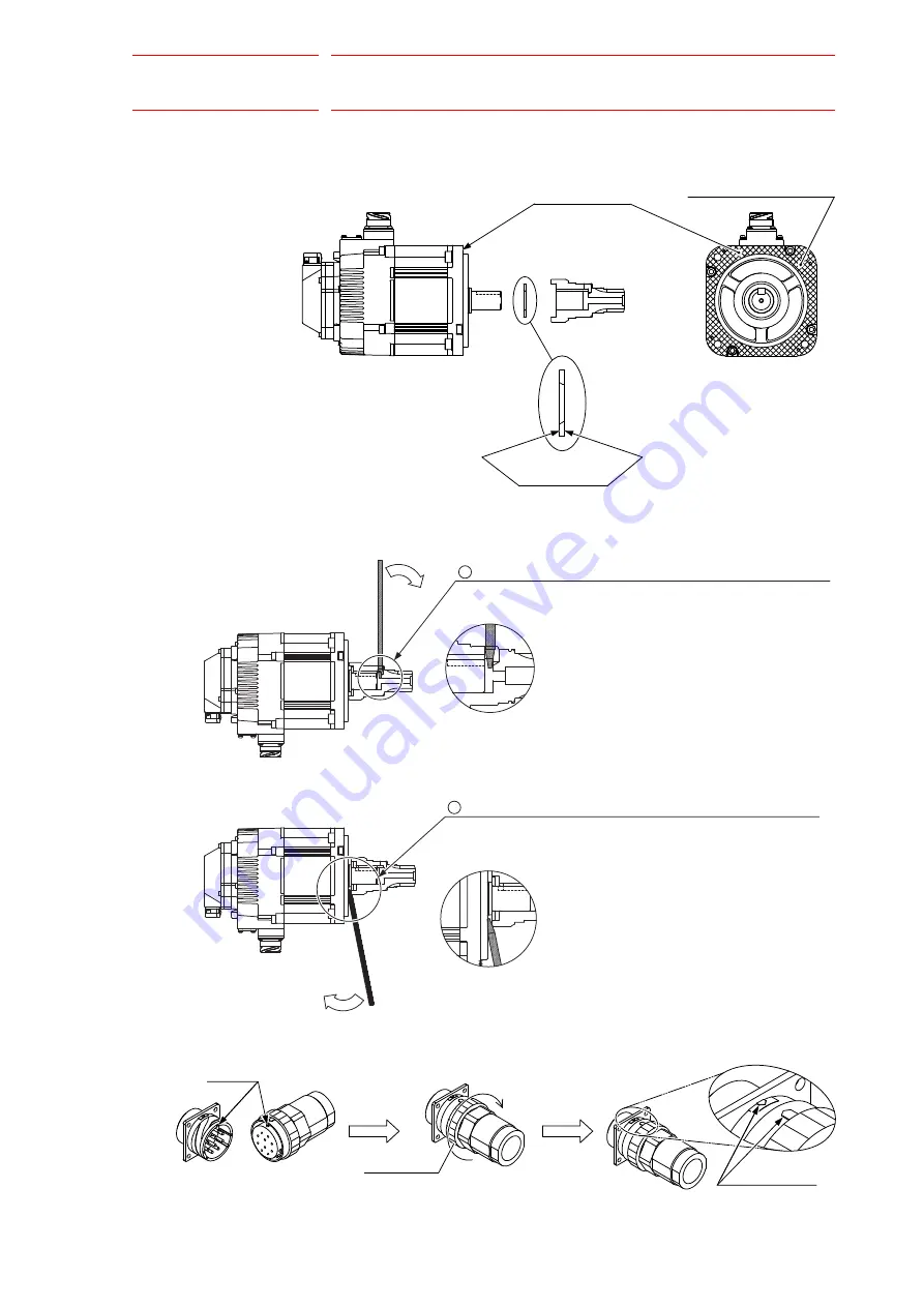
Fig. 6-5(b): Surface to Apply Sealing Bond on the R-, B-, and T-Axis
Motors
Fig. 6-5(c): Removing the Key and Gear
Fig. 6-5(d): Motor Power Cable
Surface to apply
sealing bond 2
Apply sealing bond evenly
to whole surface.
Surface to apply
sealing bond 1
Put the flat head screw driver into a space between the gear and
the motor, and tilt it in the direction of the arrow to remove the gear.
Put the flat head screw driver into the hole of the side of the gear
and tilt it in the direction of the arrow mark to make a space
between the gear and the motor.
1
2
Main key
Coupling nut
Alignment mark
63/134


