6-2
155492-1CD
HW0484820
SDA20
6 Allowable Load for Wrist Axis and Wrist Flange
6.2 Wrist Flange
6.2
Wrist Flange
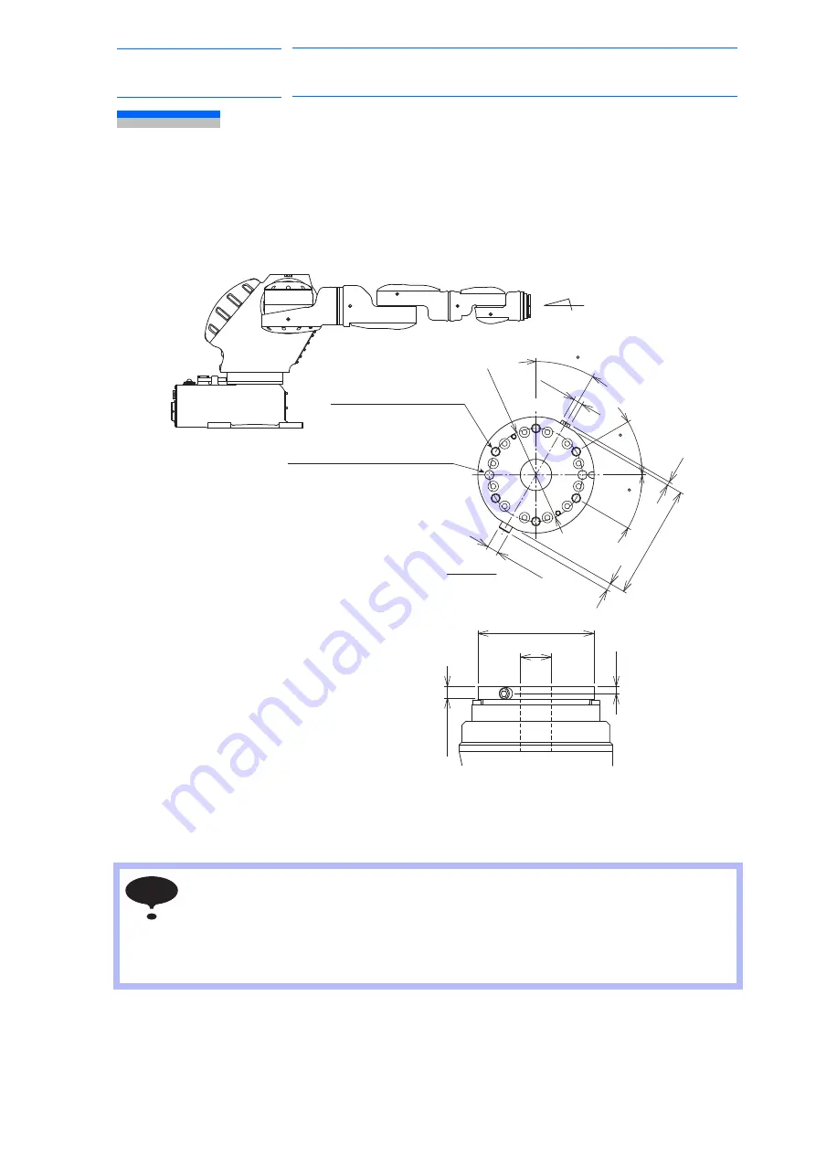
The wrist flange dimensions are shown in
.
When using the outside fitting, the depth of outside fitting must be 10 mm or less.
Fig. 6-2: Wrist Flange
• Wash off anti-corrosive paint (Yellow) on the wrist flange surface with thinner or light oil
before mounting the tools.
• When mounting an attachment, use a screw which will not go beyond 12 mm of the
tapped hole to avoid any possible adverse affect on the manipulator performance.
• Each flange has a cable through hole. When mounting equipment such as an attach-
ment, ensure that no foreign objects including liquid, oil, or dust go into the hole.
View A
(Enlarged)
P
.C.D.80
8.25
6
3
10 dia.
98
27 dia.
6
10.5
Units: mm
(Range where the dimension
100 dia. is available)
0 -0.035
100 dia.
0
-0.035
Note 1
Note 1
(diagonal)
8 dia. hole for positioning
(depth: 10mm) (2 holes)
+0.015
0
30
30
30
A
(equally-spaced)
Tapped hole M8
(depth: 12mm) (6 holes)
[Note 1]
When 100 dia. part is used,
pay attention to the screw & plug
for T-axis grease replenishment.
0
-0.035
NOTE
35 of 66


