5
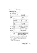
Basic Specifications
5.2 Part Names and Working Axes
5-2
175873-1CD
HW1483557
VS100
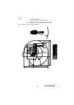
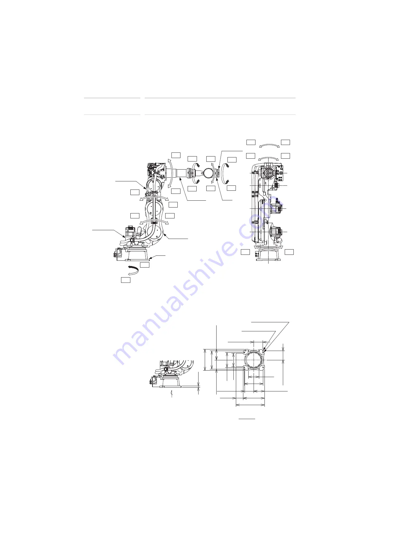
5.2
Part Names and Working Axes
Fig. 5-1: Part Names and Working Axes
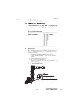
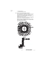
5.3
Manipulator Base Dimensions
Fig. 5-2: Manipulator Base Dimensions
S+
S-
/
L-
U-
U+
R+
R-
B+
B-
E+
E-
T+
T-
T+
T-
R+
R-
S+
S-
Middle arm
(L-armB)
Lower arm
(L-arm A)
Base
Rotary head
(S-head )
Upper arm
(U-arm)
Wrist
Wrist flange
A
22dia. hole (8 holes)
30
195±0.2
280
153
455
608
455
230±0.2
385
320
195±0.2
195±0.2
230±0.2
195±0.2
400
230
View A
12 dia. hole
+0.018
0
(2 holes )
30 of 91


