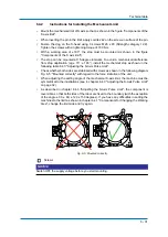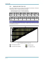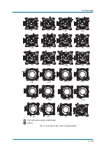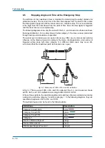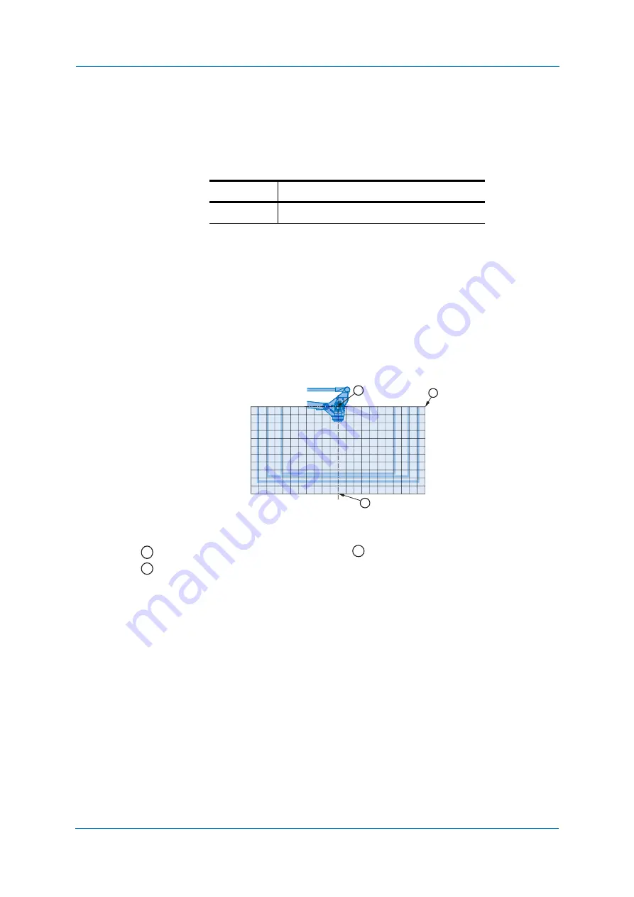
Allowable load for wrist axis and wrist flange
7
-
40
7.4
Allowable Wrist Load
The allowable wrist load including the weight of the mount/gripper is 160 kg maximum.
1. The total inertia (GD
2/4
) of T-axis should be within the given value.
2. When the inertia of the volume load on the flange is small, the eccentricity of load center
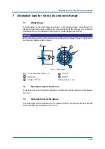
measured from T-axis flange rotation center is in the range shown in fig. Moment of arm
rating at page 46. When the inertia of the volume load on the flange (Ji) is large, use
the following formula to calculate the eccentricity L
T
.
J = Ji + WL
T²
J: Total moment of inertia (GD2/4) of the T-axis (kgm²)
Ji: Inertia of the volume load on flange (kgm²)
W: Payload (kg)
L
T
: Eccentricity (mm)
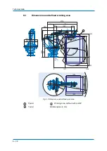
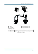
Fig. 7-2: Moment of arm rating
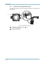
In order to facilitate the user's system applications , the peripheral equipment mounts and
tapped holes are provided on the wrist unit Fig. 7-3: "Installing peripheral equipment
mounts".
The following conditions should be observed to attach or install peripheral equipment Tab.
7-1: "Installation Conditions".
Allowed moment and maximum moment of inertia
Axis
Permissible moment of inertia (kgm²)
T-axis
80 kgm²
P point
B-axis rotation center line
R-, T-axes rotation center line
All dimensions in mm
200
200
400
600
800
1000
LB (mm)
LT (mm)
800 600 400
200
400
600
800 1000
W=160 kg
W=100 kg
W=80 kg
1
3
2
1000
1
3
2
Summary of Contents for MPL160-J00
Page 1: ...ROBOTICS MPL160 J00 YR MPL0160 J00 Operating and Maintenance Manual...
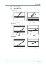
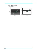
Page 36: ...Technical data 6 36 6 5 1 2 Stop position L axis 100 deflection deg deg s deg s sec...
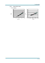
Page 37: ...Technical data 6 37 6 5 1 3 Stop position U axis 100 deflection deg deg s deg s sec...
Page 61: ...Maintenance and inspection 9 61 Air outlet cap Joint 80 9 0 170 1 1 2 2 2 1 2...
Page 91: ...Parts lists 11 91...


