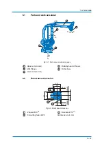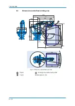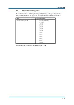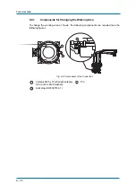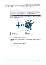
Allowable load for wrist axis and wrist flange
7
-
41
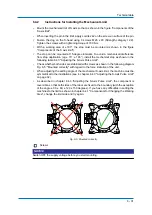
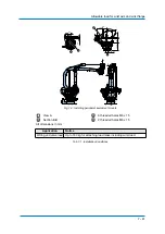
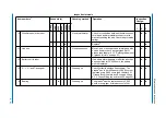
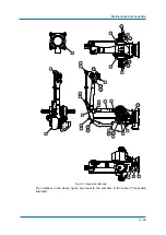
Fig. 7-3: Installing peripheral equipment mounts
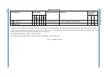
Tab. 7-1: Installation Conditions
View A
6 threaded holes M6 x 15
Section B-B
2 threaded holes M6 x 15
All dimensions in mm
Application
Notice
Wiring and valve load Up to 160 kg for attaching load mass including wrist load.
20
122
20
20
177,5
122,5
30
53
B
B'
A
1
2
3
4
Ø 53
1
3
2
4
Summary of Contents for MPL160-J00
Page 1: ...ROBOTICS MPL160 J00 YR MPL0160 J00 Operating and Maintenance Manual...
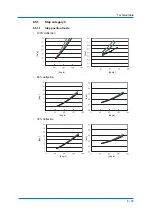
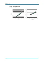
Page 36: ...Technical data 6 36 6 5 1 2 Stop position L axis 100 deflection deg deg s deg s sec...
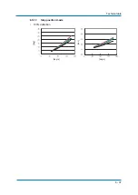
Page 37: ...Technical data 6 37 6 5 1 3 Stop position U axis 100 deflection deg deg s deg s sec...
Page 61: ...Maintenance and inspection 9 61 Air outlet cap Joint 80 9 0 170 1 1 2 2 2 1 2...
Page 91: ...Parts lists 11 91...

