Wiring
5
-
24
5.2.2
Connection of the robot controller
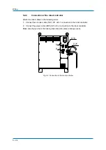
Attach the robot cables in the following order.
1. Connect the encoder cable (1BC) X11 at X-1 connection to the robot controller.
2. Connect the power cable (2BC) X21 at X-2 connection to the robot controller.
Make sure that you hear the locking clips snap into place (clicking sound).
Fig. 5-4: Connection of the robot controller
X 11
X 21
X -1
X -2
Summary of Contents for MPL500-J00
Page 1: ...ROBOTICS MPL500 J00 YR MPL0500 J00 Operating and Maintenance Manual ...
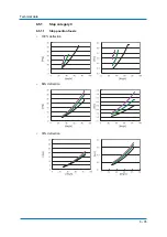
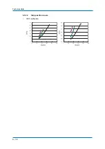
Page 36: ...Technical data 6 36 6 5 1 2 Stop position L axis 100 deflection ...
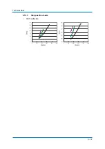
Page 37: ...Technical data 6 37 6 5 1 3 Stop position U axis 100 deflection ...
Page 61: ...Maintenance and inspection 9 61 Air outlet cap Joint 80 9 0 170 1 1 2 2 2 1 2 ...


