background image

Summary of Contents for PROFINET V1000

Page 1: ......

Page 2: ...or otherwise without the prior written permission of Yaskawa No patent liability is assumed with respect to the use of the information contained herein Moreover because Yaskawa is constantly striving...

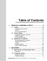
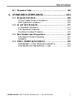
Page 3: ...ges 13 Drive Label Warnings 17 i 3 Application Precautions 18 General Application Precautions 18 Installation Environment 19 Settings 20 General Handling 20 Notes on Motor Operation 22 1 RECEIVING 27...

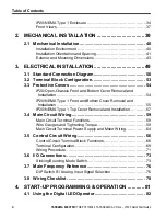
Page 4: ...tion 55 IP20 NEMA Type 1 Top Cover Removal and Installation 57 3 4 Main Circuit Wiring 59 Main Circuit Terminal Functions 59 Wire Gauges and Tightening Torque 59 Main Circuit Terminal Power Supply and...

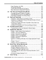
Page 5: ...Up the Drive and Operation Status Display 95 4 5 Application Selection 96 Setting 1 Water Supply Pump Application 96 Setting 2 Conveyor Application 97 Setting 3 Exhaust Fan Application 98 Setting 4 H...

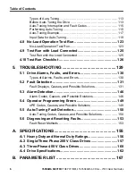
Page 6: ...t Detection 131 Fault Displays Causes and Possible Solutions 131 5 3 Alarm Detection 146 Alarm Codes Causes and Possible Solutions 146 5 4 Operator Programming Errors 149 oPE Codes Causes and Possible...

Page 7: ...andards Compliance 211 CSA Standards Compliance 218 Drive Motor Overload Protection 219 C 3 Safe Disable Input Precautions 221 Safe Disable Function Description 221 Installation 221 C 4 V1000 ORIENTA...

Page 8: ...Table of Contents This Page Intentionally Blank 8 YASKAWA ELECTRIC TOEP C710606 47A YASKAWA AC Drive V1000 Quick Start Guide...

Page 9: ...not heeded may result in fatality personal injury or equipment damage Yaskawa is not responsible for the consequences of ignoring these instructions i 1 PREFACE 10 i 2 GENERAL SAFETY 12 i 3 APPLICATIO...

Page 10: ...of its products in conforming to standards and specifications published in the Yaskawa manual NO OTHER WARRANTY EXPRESS OR IMPLIED IS OFFERED Yaskawa assumes no liability for any personal injury prop...

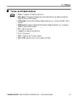
Page 11: ...Interior Permanent Magnet Motor e g Yaskawa SSR1 Series motor SPM motor Surface Mounted Permanent Magnet Motor e g Yaskawa SMRA Series SPM motor PG Pulse Generator r min Revolutions per Minute V f V...

Page 12: ...vide the manual number shown on the front cover If nameplate becomes worn or damaged order a replacement from your Yaskawa representative or the nearest Yaskawa sales office WARNING Read and understan...

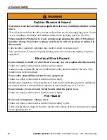
Page 13: ...any is responsible for any injuries or equipment damage resulting from failure to heed the warnings in this manual Electrical Shock Hazard Do not connect or disconnect wiring while the power is on Fai...

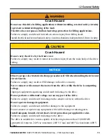
Page 14: ...plained in this manual Failure to comply could result in death or serious injury Yaskawa is not responsible for any modification of the product made by the user This product must not be modified Do no...

Page 15: ...SD damage to the drive circuitry Never connect or disconnect the motor from the drive while the drive is outputting voltage Improper equipment sequencing could result in damage to the drive Do not per...

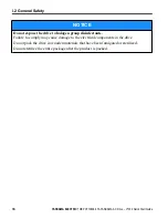
Page 16: ...damage to the electrical components in the drive Do not pack the drive in wooden materials that have been fumigated or sterilized Do not sterilize the entire package after the product is packed i 2 Ge...

Page 17: ...al before installing Wait 5 minutes for capacitor discharge after disconnecting power supply To conform to requirements make sure to ground the supply neutral for 400V class Figure i 1 Warning Informa...

Page 18: ...eactor unnecessary Figure i 3 Installing a Reactor n Drive Capacity Make sure that the motor rated current is less than the rated nameplate output current of the drive When running more than one motor...

Page 19: ...n audible noise is not a concern The user can also choose to reduce the load increase the acceleration and deceleration times or switch to a larger drive This will help keep peak current levels under...

Page 20: ...General Handling NOTICE Wiring Check Never connect the power supply lines to output terminals U T1 V T2 or W T3 Doing so will destroy the drive Be sure to perform a final check of all control wiring...

Page 21: ...n the drive warning label after opening the load switch on the output side before any inspection or maintenance of permanent magnet PM motors Failure to comply could result in death or serious injury...

Page 22: ...100 continuous torque is needed at low speeds 50 3 6 60 60 70 80 90 100 25 ED or 15 min 40 ED or 20 min 60 ED or 40 min Frequency Hz Continuous operation Torque 20 Figure i 4 Allowable Load Character...

Page 23: ...opposite direction of the Run command depending on parameter settings and motor type The amount of starting torque that can be generated differs by each control mode and by the type of motor being use...

Page 24: ...r make sure the encoder is also explosion proof Use an insulating signal converter for connecting the encoder signal lines to the drives speed feedback option card Geared Motor To avoid gear damage wh...

Page 25: ...ial used in gear box type systems to accelerate and decelerate power driven machinery Caution should also be taken when operating at speeds above the rated machine speed due to noise and shortened per...

Page 26: ...i 3 Application Precautions This Page Intentionally Blank 26 YASKAWA ELECTRIC TOEP C710606 47A YASKAWA AC Drive V1000 Quick Start Guide...

Page 27: ...ections to perform after receiving the drive and illustrates the different enclosure types and components 1 1 MODEL NUMBER AND NAMEPLATE CHECK 28 1 2 COMPONENT NAMES 31 1 YASKAWA ELECTRIC TOEP C710606...

Page 28: ...your supplier u Nameplate PRG 5010 IND CONT EQ 7J48 B CIMR V 2A0003BAA YASKAWAELECTRIC CORPORATION MADE IN JAPAN PASS AC3PH 200 240V 50 60Hz 2 7A 1 4A AC3PH 0 240V 0 400Hz 1 2A 0 8A 0 6 kg E131457 IP...

Page 29: ...fication 3 A M N S Standard Humidity and dust resistant Oil resistant Vibration resistant No Enclosure Type IP00 Open Chassis B A IP20 Open Chassis F IP20 NEMA Type 1 J IP20 Finless 2 L IP00 Finless 2...

Page 30: ...0 0056 11 47 0 0069 18 5 69 0 0069 15 60 0 n Three Phase 400 V Normal Duty Heavy Duty No Max Motor Capacity kW Rated Output Current A No Max Motor Capacity kW Rated Output Current A 0001 0 4 1 2 0001...

Page 31: ...oard Refer to Control Circuit Terminal Block Functions on page 66 F Terminal cover G Front cover screw H Front cover I Comm port J LED operator Refer to Using the Digital LED Operator on page 82 K Cas...

Page 32: ...tions on page 66 G Front cover screw H Front cover I Terminal cover J Bottom cover K LED operator Refer to Using the Digital LED Operator on page 82 L Case M Cooling fan 1 Figure 1 3 Exploded view of...

Page 33: ...erminal board Refer to Control Circuit Terminal Block Functions on page 66 G Bottom cover H Front cover screw I Front cover J Terminal cover K Comm port L LED operator Refer to Using the Digital LED O...

Page 34: ...66 F Bottom cover screws G Rubber bushing H Bottom front cover I Front cover screws J Front cover K Comm port L LED operator Refer to Using the Digital LED Operator on page 82 M Case N Top cover O Coo...

Page 35: ...ubber bushing H Bottom cover I Front cover screws J Front cover K Terminal cover L Comm port M LED operator Refer to Using the Digital LED Operator on page 82 N Case O Top cover P Cooling fan 1 Figure...

Page 36: ...Rubber bushing H Bottom cover I Front cover screws J Terminal cover K Terminal board Refer to Control Circuit Terminal Block Functions on page 66 L Front cover M Comm port N LED operator Refer to Usin...

Page 37: ...to Sinking Sourcing Mode Switch on page 73 D Control circuit terminal Refer to Control Circuit Wiring on page 66 E Main circuit terminal Refer to Wiring the Main Circuit Terminal on page 65 F Ground...

Page 38: ...1 2 Component Names This Page Intentionally Blank 38 YASKAWA ELECTRIC TOEP C710606 47A YASKAWA AC Drive V1000 Quick Start Guide...

Page 39: ...Mechanical Installation This chapter explains how to properly mount and install the drive 2 1 MECHANICAL INSTALLATION 40 2 YASKAWA ELECTRIC TOEP C710606 47A YASKAWA AC Drive V1000 Quick Start Guide 39...

Page 40: ...e in an area free from oil mist and dust metal shavings oil water or other foreign materials radioactive materials combustible materials e g wood harmful gases and liquids excessive vibration chloride...

Page 41: ...iring Install the heatsink against a closed surface to avoid diverting cooling air around the heatsink A A B C C Top Bottom Clearance Side Clearance A 30 mm minimum B Airflow direction C 100 mm minimu...

Page 42: ...2 3 Space Between Drives Side by Side Mounting Note When installing drives of different heights in the same enclosure panel the tops of the drives should line up Leave space between the top and bottom...

Page 43: ...6 0 12 1 3 BA0002B 2 68 5 04 2 99 2 20 4 65 0 20 0 26 0 12 1 3 BA0003B 2 68 5 04 4 65 2 20 4 65 0 20 1 52 0 20 2 2 Three Phase 200 V Class 2A0001B 2 68 5 04 2 99 2 20 4 65 0 20 2 26 0 12 1 3 2A0002B 2...

Page 44: ...8 3 78 4 65 0 20 2 28 0 20 3 7 2A0012B 4 25 5 04 5 41 3 78 4 65 0 20 2 28 0 20 3 7 2A0020B 5 51 5 04 5 63 5 04 4 65 0 20 2 56 0 20 5 3 Three Phase 400 V Class 4A0001B 4 25 5 04 3 19 3 78 4 65 0 20 0 3...

Page 45: ...5 2 2 M5 0 2 7 9 2A0056A 7 1 11 2 6 4 6 3 10 6 11 2 0 6 3 0 M5 0 2 11 7 2A0069A 8 7 13 2 7 4 7 6 12 6 13 2 0 6 3 1 M6 0 2 19 2 Three Phase 400 V Class 4A0018A 5 5 9 7 5 5 4 8 9 2 9 8 0 5 2 2 M5 0 2 7...

Page 46: ...4 65 0 16 0 79 0 20 0 06 0 26 0 12 1 8 BA0003F 2 68 5 89 4 65 2 20 5 03 4 65 0 16 0 79 0 20 0 06 1 54 0 20 2 6 Three Phase 200 V Class 2A0001F 2 68 5 89 2 99 2 20 5 03 4 65 0 16 0 79 0 20 0 06 0 26 0...

Page 47: ...25 5 89 5 41 3 78 5 03 4 65 0 16 0 79 0 20 0 06 2 28 0 20 4 2 2A0020F 5 51 6 02 5 63 5 04 5 03 4 65 0 19 0 79 0 20 0 20 2 56 0 20 5 7 Three Phase 400 V Class 4A0001F 4 25 5 89 3 19 3 78 5 03 4 65 0 16...

Page 48: ...6 30 10 63 11 18 0 24 0 59 0 51 0 06 2 95 0 20 M5 12 1 2A0069F 8 66 13 78 7 36 7 56 12 60 13 23 0 28 0 59 0 87 0 06 3 07 0 20 M5 20 3 Three Phase 400 V Class 4A0018F 5 51 10 00 5 51 4 80 9 21 9 76 0...

Page 49: ...supply 3 1 STANDARD CONNECTION DIAGRAM 50 3 2 TERMINAL BLOCK CONFIGURATION 53 3 3 PROTECTIVE COVERS 54 3 4 MAIN CIRCUIT WIRING 59 3 5 CONTROL CIRCUIT WIRING 66 3 6 I O CONNECTIONS 73 3 7 MAIN FREQUEN...

Page 50: ...mperes 240 Vac maximum 200 V Class and 480 Vac maximum 400 V Class NOTICE When the wiring distance is greater than 100 meters pay special attention to the motor insulation voltage or use a drive duty...

Page 51: ...2 to 50 mA default setting Pulse train output 0 to 10 Vdc 2 mA Comm connector AM AC AM 0 to 32 kHz Analog monitor output Termination resistor Monitor output 6 IG R R S S MEMOBUS Modbus comm RS 485 42...

Page 52: ...Wire H1 05 0 Improper sequencing of run stop circuitry could result in death or serious injury from moving equipment WARNING Sudden Movement Hazard Ensure start stop and safety circuits are wired pro...

Page 53: ...006 Models CIMR V BA0006 0010 0012 CIMR V 2A0010 0012 0020 CIMR V 4A0001 0002 0004 0005 0007 0009 0011 Models CIMR V 2A0030 0040 CIMR V 4A0018 0023 Model CIMR V 2A0069 Model CIMR V BA0018 Models CIMR...

Page 54: ...1 Loosen the screw that locks the front cover in place to remove Figure 3 4 Remove the Front Cover on an IP20 Open Chassis Drive 2 Apply pressure to the tabs on each side of the terminal cover Pull t...

Page 55: ...en Chassis Drive u IP20 NEMA Type 1 Front and Bottom Cover Removal and Installation n Removing the Protective Covers on an IP20 NEMA Type 1 Design 1 Loosen the screw on the front cover to remove the f...

Page 56: ...on an IP20 NEMA Type 1 Drive 3 Loosen two screws attaching the conduit bracket to remove A A Conduit bracket Figure 3 9 Remove the Conduit Bracket on an IP20 NEMA Type 1 Drive 3 3 Protective Covers 56...

Page 57: ...Type 1 Top Cover Removal and Installation To improve the ambient temperature rating of a NEMA Type 1 drive from 40 C to 50 C or to mount NEMA Type 1 drives side by side the top cover can be removed R...

Page 58: ...the top cover with the connection tabs on the drive Pinch in on the top cover to click the cover into place on the drive Connection tabs Figure 3 12 Reattaching the Top Cover 3 3 Protective Covers 58...

Page 59: ...his terminal 2 1 DC power supply input For connecting a DC power supply 2 terminals Ground Grounding Terminal 64 u Wire Gauges and Tightening Torque Select the appropriate wires and crimp terminals fr...

Page 60: ...L2 T L3 12 14 to 10 M4 1 2 to 1 5 10 6 to 13 3 U T1 V T2 W T3 14 14 to 10 1 2 14 to 10 B1 B2 14 to 10 10 14 to 10 0010 R L1 S L2 T L3 10 14 to 10 M4 1 2 to 1 5 10 6 to 13 3 U T1 V T2 W T3 14 14 to 10...

Page 61: ...V T2 W T3 14 14 to 10 1 2 14 to 10 B1 B2 14 to 10 10 14 to 10 0012 R L1 S L2 T L3 12 14 to 10 M4 1 2 to 1 5 10 6 to 13 3 U T1 V T2 W T3 14 14 to 10 1 2 14 to 10 B1 B2 14 to 10 10 14 to 10 0020 R L1 S...

Page 62: ...97 4 U T1 V T2 W T3 3 8 to 2 1 2 8 to 2 B1 B2 8 to 6 M5 2 7 to 3 0 23 9 to 26 6 6 6 to 4 M6 4 to 6 35 4 to 53 1 n Three Phase 400 V Class Table 3 4 Wire Gauge and Torque Specifications Model CIMR Vo4A...

Page 63: ...7 7 to 22 1 0023 R L1 S L2 T L3 10 10 to 6 M4 2 1 to 2 3 18 6 to 20 4 U T1 V T2 W T3 10 10 to 6 1 2 10 to 6 B1 B2 14 to 10 8 10 to 6 M5 2 to 2 5 17 7 to 22 1 0031 R L1 S L2 T L3 8 10 to 6 M5 2 7 to 3...

Page 64: ...ce the ground currents Refer to Table 3 5 to set the carrier frequency to an appropriate level Table 3 5 Cable Length Between Drive and Motor Cable Length 50 m or less 100 m or less Greater than 100 m...

Page 65: ...ailure to comply may result in death or serious injury Note A cover placed over the DC Bus and braking circuit terminals prior to shipment helps prevent miswiring Cut away covers as needed for termina...

Page 66: ...Terminals Type No Terminal Name Function Function Signal Level Default Setting Multi Function Digital Inputs S1 Multi function input 1 Closed Forward run Open Stop Photocoupler 24 Vdc 8 mA Note Drive...

Page 67: ...1 A 250 Vac 10 mA to 1 A Minimum load 5 Vdc 10 mA reference value MB N C output fault MC Digital output common Multi Function Photocoupler Output P1 Photocoupler output 1 During run Photocoupler outpu...

Page 68: ...nal Name Function Signal Level MEMOBUS Modbus Communication R Communications input MEMOBUS Modbus communication Use a RS 485 or RS 422 cable to connect the drive RS 485 422 MEMOBUS Modbus communicatio...

Page 69: ...MB MA S1 S2 S3 S4 S5 S6 S7 HC SC H1 RP R R S S IG P1 P2 PC A1 A2 V AC AM AC MP MC MB MA Figure 3 15 Removable Control Circuit Terminal Block CIMR VAooooooo CIMR VUooooooo 3 5 Control Circuit Wiring YA...

Page 70: ...Type MA MB MC M3 0 5 to 0 6 4 4 to 5 3 Stranded 0 25 to 1 5 24 to 16 Single 0 25 to 1 5 24 to 16 0 75 18 0 25 to 1 0 24 to 17 0 5 20 Shielded line etc S1 S7 SC RP V A1 A2 AC HC H1 P1 P2 PC MP AM AC S...

Page 71: ...rd when connecting to the control terminals Improper application of peripheral devices could result in drive performance degradation due to improper power supply NOTICE Insulate shields with tape or s...

Page 72: ...e E Blade depth of 0 4 mm or less Blade width of 2 5 mm or less Figure 3 17 Terminal Board Wiring Guide A F C D E B A Drive side B Connect shield to ground terminal of drive C Insulation D Control dev...

Page 73: ...d sourcing mode the drive is preset to sinking mode Table 3 11 Sinking Sourcing Mode Setting Set Value Details SINK Sinking Mode 0 V common default setting SOURCE Sourcing Mode 24 V common DIP Switch...

Page 74: ...ower supply Drive Shielded cable Forward run stop Reverse run stop External fault N O Fault reset Multi speed step 1 Multi speed step 2 Jog reference Multi function input S1 S2 S3 S3 24V S4 S5 S6 S7 S...

Page 75: ...top Reverse run stop External fault N O Fault rest Multi step speed 1 Multi step speed 2 Jog frequency External power supply Shielded cable Drive Multi function input S1 S2 S3 24V S4 S5 S6 S7 SC S3 SI...

Page 76: ...or 0 20 mA Set parameter H3 10 0 frequency reference Note If Terminals A1 and A2 are both set for frequency reference H3 02 0 and H3 10 0 the addition of both input values builds the frequency refere...

Page 77: ...9 Details No Parameter Name Description Setting Range Default Setting H3 09 Frequency ref current terminal A2 signal level selection Selects the signal level for terminal A2 0 0 to 10 V unipolar input...

Page 78: ...9 Properly wire the drive and motor together The motor lines and drive output terminals R T1 V T2 and W T3 should match in order to produce the desired phase order If the phase order is incorrect the...

Page 79: ...s of shielded wiring to the GND terminal 71 19 If using a 3 Wire sequence properly set parameters for multi function contact input terminals S1 through S7 and properly wire control circuits 52 20 Prop...

Page 80: ...3 8 Wiring Checklist This Page Intentionally Blank 80 YASKAWA ELECTRIC TOEP C710606 47A YASKAWA AC Drive V1000 Quick Start Guide...

Page 81: ...TOR 82 4 2 THE DRIVE AND PROGRAMMING MODES 87 4 3 START UP FLOWCHARTS 90 4 4 POWERING UP THE DRIVE 95 4 5 APPLICATION SELECTION 96 4 6 BASIC DRIVE SETUP ADJUSTMENTS 106 4 7 AUTO TUNING 113 4 8 NO LOAD...

Page 82: ...on1 Monitor Verify SetUpGuide Program Auto Tuning Read manual before installing Risk of electric shock Wait 1 minute for capacitor discharge after disconnecting power supply To conform to requirements...

Page 83: ...disable the STOP key priority 8 ENTER Key Selects all modes parameters settings etc Selects a menu item to move from one display screen to the next 9 LO RE Selection Key Switches drive control between...

Page 84: ...mage u LED Screen Displays Display Lit Flashing Off When the drive detects an alarm or error When an alarm occurs oPE detected When a fault or error occurs during Auto Tuning Normal state no fault or...

Page 85: ...As shown 1 Refer to Figure 4 1 for the difference between flashing and flashing quickly 2 Refer to the description for parameter U4 21 on page 200 for information on verifying operation interlock Fla...

Page 86: ...Mode Parameter Setting Mode Auto Tuning Description of Key Operations Note XX characters are shown in this manual The drive will display the actual setting values PROGRAMMING MODE DRIVE MODE 1 Applic...

Page 87: ...01 Acceleration Time 1 from 10 0 seconds default to 20 0 seconds Step Display Result 1 Turn on the power to the drive The initial display appears 2 Press the key until the Setup Mode Screen appears 3...

Page 88: ...he drive will not allow the user to switch between LOCAL and REMOTE during run n Using the LO RE Key on the LED Operator Step Display Result 1 Turn on the power to the drive The initial display appear...

Page 89: ...on page 96 Table 4 2 Setup Group Parameters Parameter Name A1 02 Control Method Selection b1 01 Frequency Reference Selection 1 b1 02 Run Command Selection 1 b1 03 Stop Method Selection C1 01 Acceler...

Page 90: ...rocedures Flowchart Subchart Objective Page A Basic startup procedure and motor tuning 91 A 1 Simple motor setup with Energy Savings or Speed Search using V f mode 92 A 2 High performance operation us...

Page 91: ...Flowchart A 3 b1 01 02 for frequency reference and run command source selection H1 oo H2 oo H3 oo H4 oo H6 oo for I O terminal setting d1 oo for multi speed references if used C1 oo and C2 oo C6 01 fo...

Page 92: ...otational auto tuning cannot be performed From Flowchart A Set or verify the V f pattern settings E1 oo Energy Savings b8 01 1 or Speed Estimation Speed Search b3 24 1 enabled Is the motor cable longe...

Page 93: ...e load disconnected NO YES NO Motor test report data sheet available NO YES YES Perform Rotating Auto Tuning T1 01 0 Is the motor cable longer than 50 m Perform Stationary Auto Tuning for terminal res...

Page 94: ...torque applications YES NO From Flowchart A Set the motor code to parameter E5 01 Return to Flowchart A Motorcode is known For parameter E5 01 for Yaskawa PM Motors Enter FFFF to parameter E5 01 Ente...

Page 95: ...3 with motor terminals U V and W Control circuit terminals Check control circuit terminal connections Drive control terminal status Open all control circuit terminals off Status of the load and connec...

Page 96: ...gnals and external sequence before performing a test run Setting parameter A1 06 may change the I O terminal function automatically from the default setting Failure to comply may result in death or se...

Page 97: ...ion Digital Input Terminal S7 Function Selection E1 03 V f Pattern Selection L5 01 Number of Auto Restart Attempts E1 07 Middle Output Frequency u Setting 2 Conveyor Application Table 4 5 Conveyor Par...

Page 98: ...ed Table 4 8 Exhaust Fan User Parameters A2 01 to A2 16 No Parameter Name No Parameter Name b1 01 Frequency Reference Selection 1 E1 07 Middle Output Frequency b1 02 Run Command Selection 1 E1 08 Midd...

Page 99: ...ection 1 E1 03 V f Pattern Selection b1 02 Run Command Selection 1 E1 04 Maximum Output Frequency b1 04 Reverse Operation Selection E2 01 Motor Rated Current C1 01 Acceleration Time 1 H3 11 Terminal A...

Page 100: ...ation Preset 6 2 Perform Auto Tuning after selecting Application Preset 6 3 If UL3 appears on the operator display after Auto Tuning is complete set L6 01 to 0 to repeat the Auto Tuning process Table...

Page 101: ...erence 2 b1 01 Frequency Reference Selection 1 d1 03 Frequency Reference 3 b6 01 Dwell Reference at Start E1 08 Middle Output Frequency Voltage b6 02 Dwell Time at Start H2 01 Terminals MA MB and MC F...

Page 102: ...e may be a jolt at start 2 Hysteresis for Frequency Detection 2 can be adjusted by changing the Frequency Detection Width L4 02 between 0 0 and 0 5 Hz If the load slips during stop make changes in ste...

Page 103: ...02 Deceleration Time 1 3 0 s C6 01 Drive Duty Selection 0 Heavy Duty C6 02 Carrier Frequency Selection 2 5 kHz d1 01 Frequency Reference 1 6 0 Hz d1 02 Frequency Reference 2 30 0 Hz d1 03 Frequency Re...

Page 104: ...1 06 Multi Function Digital Input Terminal S6 Function d1 01 Frequency Reference 1 H2 01 Terminals MA MB and MC Function Selection d1 02 Frequency Reference 2 L1 01 Motor Overload Protection Selection...

Page 105: ...ce Selection 1 L3 04 Stall Prevention Selection during Deceleration b1 02 Run Command Selection 1 n3 13 Overexcitation Deceleration Gain C1 01 Acceleration Time 1 n3 21 High Slip Suppression Current L...

Page 106: ...ring high precision high speed control PM Open Loop Vector Control A1 02 5 Variable torque applications employing permanent magnet motors and energy savings u Initialize Parameter Values A1 03 Paramet...

Page 107: ...e set parameters to the factory settings u Frequency Reference Source b1 01 This section explains how to assign the frequency reference Parameters b1 01 and b1 02 can be used to select the source of t...

Page 108: ...quency reference to switch between analog input A1 and A2 main aux frequency switch use the following setup 1 Set the frequency reference source to terminals b1 01 1 2 Set one of the digital inputs to...

Page 109: ...as the drive is powered up Be sure to take proper precautions if using this setting Ensure the area around the motor is safe Failure to comply could result in death or serious injury n Run the Drive...

Page 110: ...s to a complete stop flashing off n Run the Drive using Digital Input Terminals b1 02 1 This setting uses the digital input terminals to enter the run command The factory setting is a 2 Wire sequence...

Page 111: ...drive and may cause injury CAUTION The motor will begin rotating as soon as the power is switched on Proper precautions must be taken to ensure that the area around the motor is safe prior to powerin...

Page 112: ...l PWM patterns minimizes the audible noise of the motor 2 The upper limit for the carrier frequency is determined by drive capacity u Drive Input Voltage Setting E1 01 Set E1 01 according to the power...

Page 113: ...Auto Tuning has been previously performed When motor capacity and drive capacity differ V f Control Open Loop Vector Control Note Auto Tuning cannot be performed on permanent magnet motors IPM SPM etc...

Page 114: ...load the motor constants will be inaccurate and the motor may exhibit abnormal operation Disconnect or decouple the motor from the load n Notes on Rotational Auto Tuning For optimal performance Auto T...

Page 115: ...ing Interrupted Figure 4 14 Auto Tuning Interruption Display u Performing Auto Tuning n Auto Tuning Procedure Auto Tuning should generally be performed in the following steps 1 Refer to Before Auto Tu...

Page 116: ...0 START Select a V f pattern E1 03 Open Loop Vector A1 02 2 Select the Motor Control Mode A1 02 Can the load be disconnected from the motor Will the application allow motor rotation for Auto Tuning NO...

Page 117: ...op Vector Control A1 02 2 n Set the Selected Type of Auto Tuning Step Display Result 1 Turn on the power to the drive The initial display appears 2 Press the key until the Auto Tuning display appears...

Page 118: ...ard The drive and motor may start unexpectedly during Auto Tuning which could result in death or serious injury Ensure the area surrounding the drive motor and load are clear before proceeding with Au...

Page 119: ...to factory defaults 2 For motors that are to be operated in the field weakening range first perform the Auto Tuning with the base data i e the frequency at which the motor is operating with its rated...

Page 120: ...o2 04 and C6 01 1 The setting range differs based on drive software version PRG 1016 and later 0 03 to 650 00 kW PRG 1015 and earlier 0 00 to 650 00 kW n T1 03 Motor Rated Voltage T1 01 0 or 3 Used t...

Page 121: ...frequency here if known The no load frequency refers to the frequency needed to operate the motor under no load condition at its rated speed Refer to the motor data sheet No Name Setting Range Defaul...

Page 122: ...E2 10 will appear as the default in T1 11 If the value of T1 02 is not changed during Auto Tuning data input the drive will select a value that is typical for the motor power entered to T1 02 No Name...

Page 123: ...items during operation The motor should rotate smoothly i e no abnormal noise or oscillation The motor should accelerate and decelerate smoothly n No Load Operation Instructions The following example...

Page 124: ...crease the frequency in 10 Hz increments verifying smooth operation results at all speeds For each frequency monitor the drive output current U1 03 through the LED operator to confirm the current is w...

Page 125: ...list Before Operation The motor should rotate in the proper direction The motor should accelerate and decelerate smoothly n Operating the Motor under Loaded Conditions Test run the application similar...

Page 126: ...to the application and motor characteristics Example If using a motor with a rated frequency of 60 0 Hz set E1 03 to 1 5 Perform Auto Tuning for Energy Savings if using Energy Saving functions 113 Op...

Page 127: ...orrect current input signal level 4 to 20 mA or 0 to 20 mA 88 17 Set the proper voltage to terminal A1 0 to 10 V 18 Set the proper current to terminal A2 4 to 20 mA or 0 to 20 mA 19 When current input...

Page 128: ...4 10 Test Run Checklist This Page Intentionally Blank 128 YASKAWA ELECTRIC TOEP C710606 47A YASKAWA AC Drive V1000 Quick Start Guide...

Page 129: ...serve as a reference guide for tuning the drive during a trial run 5 1 DRIVE ALARMS FAULTS AND ERRORS 130 5 2 FAULT DETECTION 131 5 3 ALARM DETECTION 146 5 4 OPERATOR PROGRAMMING ERRORS 149 5 5 AUTO T...

Page 130: ...n contact outputs closes if set to be tripped by a minor fault H2 oo 10 but not by an alarm The digital operator displays text indicating a specific alarm and ALM indicator LED flashes Remove the caus...

Page 131: ...surge suppressors if required Use cables recommended by Yaskawa or another type of shielded line Ground the shield on the controller side or on the drive input power side Separate all wiring for commu...

Page 132: ...ffset value beyond the allowable range Create a motor restart sequence that allows enough time for the residual induction voltage to dissipate Enable Speed Search at start b3 01 1 Use the multi functi...

Page 133: ...version error CPF23 PWM Feedback Fault PWM feedback error CPF24 Drive Capacity Signal Fault Entered a capacity that does not exist Checked when the drive is powered up Cause Possible Solution Hardware...

Page 134: ...terminal S6 EF7 External Fault input terminal S7 External fault at multi function input terminal S7 Cause Possible Solution An external device has tripped an alarm function Remove the cause of the ext...

Page 135: ...same when using PM OLV Hardware problem Replace the drive LF Output Phase Loss Phase loss on the output side of the drive Phase Loss Detection is enabled when L8 07 is set to 1 or 2 Cause Possible So...

Page 136: ...the motor cables Remove the short circuit and power the drive back up Check the resistance between the motor cables and the ground terminal Replace damaged cables The load is too heavy Measure the cur...

Page 137: ...b3 01 1 Program the Speed Search command input through one of the multi function contact input terminals H1 oo 61 or 62 The wrong motor code has been entered for PM Open Loop Vector Yaskawa motors on...

Page 138: ...ing near the drive that might be producing excessive heat Load is too heavy Measure the output current Lower the carrier frequency C6 02 Reduce the load The internal cooling fan has reached its perfor...

Page 139: ...perate with the drive Although a special type of motor is being used the motor protection selection is set for a general purpose motor L1 01 1 Set L1 01 2 Voltage is too high for the V f characteristi...

Page 140: ...nd E1 10 Be careful not to lower E1 08 and E1 10 excessively because this reduces load tolerance at low speeds Drive capacity is too small Replace the drive with a larger model Overload occurred when...

Page 141: ...rve acceleration and deceleration times Excessive braking load The braking torque was too high causing regenerative energy to charge the DC bus Reduce the braking torque use a braking option or length...

Page 142: ...loss in the drive input power Check for wiring errors in the main circuit drive input power Correct the wiring There is loose wiring in the drive input power terminals Ensure the terminals are tighte...

Page 143: ...even when the braking resistor surface is not very hot rr Dynamic Braking Transistor The built in dynamic braking transistor failed Cause Possible Solution The braking transistor is damaged Cycle pow...

Page 144: ...Drive internal circuitry has become worn Check the maintenance time for the capacitors U4 05 Replace the drive if U4 05 exceeds 90 The drive input power transformer is not large enough and voltage dro...

Page 145: ...ault reoccurs Replace the drive if the fault continues to occur Check monitor U4 06 for the performance life of the inrush prevention circuit Replace the drive if U4 06 exceeds 90 5 2 Fault Detection...

Page 146: ...s CrST Can Not Reset CyC MECHATROLINK II Comm Cycle Setting Error Comm Cycle Setting Error was detected dEv Speed Deviation for Simple V f with PG According to the pulse input RP the speed deviation i...

Page 147: ...l 150 of the rated current LT 1 Cooling Fan Maintenance Time The cooling fan has reached its expected maintenance period and may need to be replaced Note An alarm output H2 oo 10 will only be triggere...

Page 148: ...sconnect for Simple V f with PG Detected when no PG pulses received for a time longer than setting in F1 14 rUn Motor Switch during Run A command to switch motors was entered during run SE MEMOBUS Mod...

Page 149: ...multi function analog inputs H3 02 through to H3 10 and PID functions conflict oPE08 Parameter Selection Error A function has been set that cannot be used in the motor control method selected oPE09 P...

Page 150: ...Solutions Motor data entered during Auto Tuning was incorrect Motor data entered to the T1 parameters does not match the information written on the motor nameplate Restart Auto Tuning and enter the c...

Page 151: ...essing STOP button Auto Tuning did not complete properly and will have to be performed again Er 04 Line to Line Resistance Error Cause Possible Solutions Motor data entered during Auto Tuning was inco...

Page 152: ...ing is too low L7 01 and L7 02 Check the settings of parameters L7 01 and L7 02 Increase the setting Er 11 Motor Speed Fault detected only when Auto Tuning is enabled Cause Possible Solutions Torque r...

Page 153: ...TOP Fix the cause of the fault and reset via Fault Reset Digital Input S4 Close then open the fault signal digital input via terminal S4 S4 is set fault reset as default H1 04 12 Fault Reset Switch Dr...

Page 154: ...5 6 Diagnosing and Resetting Faults This Page Intentionally Blank 154 YASKAWA ELECTRIC TOEP C710606 47A YASKAWA AC Drive V1000 Quick Start Guide...

Page 155: ...ND NORMAL DUTY RATINGS 156 A 2 SINGLE THREE PHASE 200 V CLASS DRIVES 157 A 3 THREE PHASE 400 V CLASS DRIVES 160 A 4 DRIVE SPECIFICATIONS 162 Appendix A YASKAWA ELECTRIC TOEP C710606 47A YASKAWA AC Dri...

Page 156: ...2 kHz Swing PWM 1 The following pages list information on rating changes based on drive model TERMS TERMS HD and ND HD refers to applications requiring constant torque output while ND refers to appli...

Page 157: ...Output Capacity kVA 5 ND Rating 0 5 0 7 1 3 2 3 3 7 4 6 7 5 2 HD Rating 0 3 0 6 1 1 1 9 3 0 4 2 6 7 Output Current A ND Rating 6 1 2 1 9 3 5 3 3 6 0 9 6 12 0 19 6 2 HD Rating 0 8 7 1 6 7 3 0 7 5 0 7...

Page 158: ...ual to or greater than the motor rated current 4 Input current rating varies depending on the power supply transformer input reactor wiring connections and power supply impedance 5 Rated motor capacit...

Page 159: ...Hz 400 Hz user adjustable Power Supply Rated Voltage Rated Frequency Three phase power Three phase 200 to 240 V 50 60 Hz Single phase power 200 to 240 V 50 60 Hz Allowable Voltage Fluctuation 15 to 10...

Page 160: ...that start and stop frequently Carrier Frequency User adjustable 2 to 15 kHz Maximum Output Voltage V Three phase 380 to 480 V proportional to input voltage Maximum Output Frequency Hz 400 Hz user ad...

Page 161: ...ut voltage Maximum Output Frequency Hz 400 Hz user adjustable Power Supply Rated Voltage Rated Frequency Three phase 380 to 480 V 50 60 Hz Allowable Voltage Fluctuation 15 to 10 Allowable Frequency Fl...

Page 162: ...reference 0 to 10 Vdc 20 k 4 to 20 mA 250 0 to 20 mA 250 Main speed reference Pulse Train Input max 32 kHz Starting Torque 200 0 5 Hz OLV Control HD rating IM of 3 7 kW or smaller 50 6 Hz OLV PM Contr...

Page 163: ...voltage Specification 200 V Class Stops when DC bus voltage exceeds approx 410 V 400 V Class Stops when DC bus voltage exceeds approx 820 V Low Voltage Protection Drive stops when DC bus voltage falls...

Page 164: ...put open to drive output stop is less than 1 ms Protective Enclosure IP20 Open Chassis or IP00 Open Chassis 8 IP20 NEMA Type 1 9 Cooling Method CIMR VoBA0001 to 0006 self cooled CIMR VoBA0010 to 0018...

Page 165: ...ered up from a ground short 8 The following models have an IP20 Open Chassis enclosure as standard Customers may convert these models to IP20 NEMA Type 1 enclosures using the IP20 NEMA Type 1 Kit Opti...

Page 166: ...A 4 Drive Specifications This Page Intentionally Blank 166 YASKAWA ELECTRIC TOEP C710606 47A YASKAWA AC Drive V1000 Quick Start Guide...

Page 167: ...arameter List This chapter contains a listing of all parameters available in the drive B 1 PARAMETER TABLE 168 Appendix B YASKAWA ELECTRIC TOEP C710606 47A YASKAWA AC Drive V1000 Quick Start Guide 167...

Page 168: ...meter values must be stored using parameter o2 03 2220 2 Wire Initialization 3330 3 Wire Initialization 5550 OPE04 Error Reset A1 04 Password 1 Refer to V1000 Technical Manual for details A1 05 Passwo...

Page 169: ...Braking Start Frequency Refer to V1000 Technical Manual for details b2 02 DC Injection Braking Current Sets the DC Injection Braking current as a percentage of the drive rated current b2 03 DC Injecti...

Page 170: ...b5 parameters to configure the PID control drive function b5 01 PID Function Setting 0 Disabled 1 Enable Deviation is D controlled 2 Enable Feedback is D controlled 3 Enable Deviation is D controlled...

Page 171: ...l Manual for details b5 20 PID Setpoint Scaling Refer to V1000 Technical Manual for details b5 34 PID Output Lower Limit Refer to V1000 Technical Manual for details b5 35 PID Input Limit Refer to V100...

Page 172: ...a digital input C1 06 Deceleration Time 3 Motor 2 Decel Time 1 Sets the time to decelerate from maximum frequency to 0 when Accel Decel times 3 are selected by a digital input C1 07 Acceleration Time...

Page 173: ...1000 Technical Manual for details C4 04 Torque Compensation at Reverse Start Refer to V1000 Technical Manual for details C4 05 Torque Compensation Time Constant Refer to V1000 Technical Manual for det...

Page 174: ...igital input Multi Step Speed Reference 2 H1 oo 4 is on d1 04 Frequency Reference 4 Frequency reference when digital inputs Multi Step Speed Reference 1 2 H1 oo 3 and 4 are on d1 05 Frequency Referenc...

Page 175: ...s with resonant vibration of the motor machine d3 02 Jump Frequency 2 d3 03 Jump Frequency 3 d3 04 Jump Frequency Width This parameter sets the dead band width around each selected prohibited frequenc...

Page 176: ...req Only applicable when E1 03 is set to F To set linear V f characteristics set the same values for E1 07 and E1 09 E1 08 Middle Output Frequency Voltage Only applicable when E1 03 is set to F E1 09...

Page 177: ...ils E3 10 Motor 2 Min Output Freq Voltage Refer to V1000 Technical Manual for details E3 11 Motor 2 Mid Output Frequency 2 Refer to V1000 Technical Manual for details E3 12 Motor 2 Mid Output Frequenc...

Page 178: ...rameters to set up the drive for Simple PG V f control These parameters are enabled only when H6 01 03 F1 02 Operation Selection at PG Open Circuit PGO Refer to V1000 Technical Manual for details F1 0...

Page 179: ...nical Manual for details Note Available in drive software versions PRG 1020 and later F6 26 MECHATROLINK bUS Errors Detected Refer to V1000 Technical Manual for details Note Available in drive softwar...

Page 180: ...2 DeviceNet Heartbeat Interval Refer to V1000 Technical Manual for details Note Available in drive software versions PRG 1011 and later F6 63 Dynamic Output Assembly 109 Parameter 1 Note Function avai...

Page 181: ...Technical Manual for details Dynamic Output Assembly 159 Parameter 3 Note Function available in versions PRG 1014 and later F6 71 Dynamic Output Assembly 159 Parameter 4 Note Function available in ve...

Page 182: ...peed reference Closed Jog Frequency reference d1 17 Jog has priority over all other reference sources 7 Accel Decel Time 1 Used to switch between Accel Decel Time 1 2 8 Baseblock Command N O Open Norm...

Page 183: ...ays Detected Coast To Stop 25 N C Always Detected Coast To Stop 26 N O During Run Coast To Stop 27 N C During Run Coast To Stop 28 N O Always Detected Fast stop 29 N C Always Detected Fast stop 2A N O...

Page 184: ...de Thru 1 enabled 67 Communications Test Mode Tests the MEMOBUS Modbus RS 485 422 interface 68 High Slip Braking Closed High Slip braking is executed Drive stops 6A Drive Enable Open Drive disabled If...

Page 185: ...resis determined by L4 02 6 Drive Ready Closed Drive Ready The drive is powered up not in a fault state and in the Drive mode 7 DC Bus Undervoltage Closed DC bus voltage is below the UV trip level set...

Page 186: ...1C Motor 2 Selection Closed Motor 2 is selected by a digital input H1 oo 16 1E Restart Enabled Closed An automatic restart is performed 1F Motor Overload Alarm oL1 Closed OL1 is at 90 of its trip poin...

Page 187: ...on Sets the function of terminal A1 H3 03 Terminal A1 Gain Setting Sets the level of the input value selected in H3 02 when 10V is input at terminal A1 H3 04 Terminal A1 Bias Setting Sets the level of...

Page 188: ...Motor rated torque V f control Drive rated current B PID Feedback 10V 100 C PID Set Point 10V 100 E Motor Temperature PTC input 10 V 100 00 F Not used Through Mode 10 FWD Torque Limit Motor rated tor...

Page 189: ...bled RTS is always on 1 Enabled RTS turns on only when sending H5 09 CE Detection Time Refer to V1000 Technical Manual for details H5 10 Unit Selection for MEMOBUS Modbus Register 0025H Refer to V1000...

Page 190: ...ration Selection PTC input Refer to V1000 Technical Manual for details L1 05 Motor Temperature Input Filter Time PTC input Refer to V1000 Technical Manual for details L1 13 Continuous Electrothermal O...

Page 191: ...in drive software versions PRG 1020 and later L3 05 Stall Prevention Selection during Run 0 Disabled 1 Decel Time 1 2 Decel Time 2 L3 06 Stall Prevention Level during Run Enabled when L3 05 is set to...

Page 192: ...rt Attempts Sets the counter for the number of times the drive attempts to restart when the following faults occur gF LF oC oV PF PUF rH rr oL1 oL2 oL3 oL4 Uv1 L5 02 Auto Restart Operation Selection R...

Page 193: ...al Dynamic Braking Resistor Protection Selection ERF type 0 Resistor overheat protection disabled 1 Resistor overheat protection enabled L8 02 Overheat Alarm Level Refer to V1000 Technical Manual for...

Page 194: ...on Time Constant Refer to V1000 Technical Manual for details n1 05 Hunting Prevention Gain while in Reverse Refer to V1000 Technical Manual for details n2 Speed Feedback Detection Control Function Use...

Page 195: ...ck Detection Control Gain during ov Suppression Refer to V1000 Technical Manual for details Note Available in drive software versions PRG 1011 and later n8 68 Output Voltage Limit Gain 2 Refer to V100...

Page 196: ...gital Operator is Disconnected 0 The drive will continue operation 1 The drive will trigger a fault oPr and the motor will coast to stop o2 07 Motor Direction at Power Up when Using Operator Refer to...

Page 197: ...rated voltage in volts V T1 04 Motor Rated Current Sets the motor rated current in amperes A T1 05 Motor Base Frequency Sets the base frequency of the motor in Hertz Hz T1 06 Number of Motor Poles Set...

Page 198: ...lt trace data U2 01 Current Fault Display of the current fault U2 02 Previous Fault Display of the previous fault U2 03 Frequency Reference at Previous Fault Displays the frequency reference at the pr...

Page 199: ...lative Operation Time at Most Recent Fault Displays the cumulative operation time at the most recent fault U3 12 Cumulative Operation Time at 2nd Most Recent Fault Displays the cumulative operation ti...

Page 200: ...te OL1 100 OL1 detection level U4 18 Frequency Reference Source Selection Refer to V1000 Technical Manual for details U4 19 Frequency Reference from MEMOBUS Modbus Comm Refer to V1000 Technical Manual...

Page 201: ...Down 2 Refer to V1000 Technical Manual for details U6 21 Offset Frequency Refer to V1000 Technical Manual for details U6 80 to U6 99 Option Monitors 1 to 20 Refer to the V1000 Option Technical Manual...

Page 202: ...B 1 Parameter Table This Page Intentionally Blank 202 YASKAWA ELECTRIC TOEP C710606 47A YASKAWA AC Drive V1000 Quick Start Guide...

Page 203: ...criteria for maintaining CE and UL standards C 1 EUROPEAN STANDARDS 204 C 2 UL AND CSA STANDARDS 211 C 3 SAFE DISABLE INPUT PRECAUTIONS 221 C 4 V1000 ORIENTA O B SICA 223 Appendix C YASKAWA ELECTRIC...

Page 204: ...irective Compliance This drive has been tested according to European standard EN50178 and it fully complies with the Low Voltage Directive To comply with the Low Voltage Directive be sure to meet the...

Page 205: ...ns to ensure that other devices and machinery used in combination with this drive also comply with EMC guidelines 1 Install an EMC noise filter to the input side specified by Yaskawa for compliance wi...

Page 206: ...l plate D Grounding surface remove any paint or sealant E Drive F Motor cable braided shield cable max 20 m G Motor H Cable clamp I Wiring distance as short as possible J EMC noise filter Figure C 2 E...

Page 207: ...ax 20 m G Motor H Cable clamp I Wiring distance as short as possible J EMC noise filter Figure C 3 EMC Filter and Drive Installation for CE Compliance Single Phase 200 V Class n EMC Filters The drive...

Page 208: ...14 07 14 1 28 4 4 x 6 7 x 1 8 3 6 x 6 1 M4 M5 2A0012 FS23637 14 07 14 1 28 4 4 x 6 7 x 1 8 3 6 x 6 1 M4 M5 2A0020 FS23637 24 07 24 1 98 5 7 x 6 9 x 2 0 4 7 x 6 1 M4 M5 2A0030 FS23637 52 07 52 4 41 5...

Page 209: ...models CIMR VoBA0018 and 2A0030 through 0069 are in compliance with IEC61800 3 Category 2 All other models comply with Category 1 H X L W Y LINE A PE LOAD Figure C 4 EMC Filter Dimensions n DC Link C...

Page 210: ...0 V Three Phase Units 4A0002 UZDA B 3 2 A 28 mH 4A0004 Note Models not listed in the above table do not require a DC link choke for EMC compliance C 1 European Standards 210 YASKAWA ELECTRIC TOEP C710...

Page 211: ...all the drive to an area greater than pollution severity 2 UL standard n Ambient Temperature IP20 NEMA Type 1 enclosure 10 C to 40 C IP20 IP00 Open Chassis enclosure 10 C to 50 C Finless Type IP20 IP0...

Page 212: ...T2 W T3 14 14 to 10 1 2 14 to 10 B1 B2 14 to 10 10 14 to 10 0010 R L1 S L2 T L3 10 14 to 10 M4 1 2 to 1 5 10 6 to 13 3 U T1 V T2 W T3 14 14 to 10 1 2 14 to 10 B1 B2 14 to 10 10 14 to 10 0012 R L1 S L2...

Page 213: ...14 to 10 M4 1 2 to 1 5 10 6 to 13 3 U T1 V T2 W T3 14 14 to 10 1 2 14 to 10 B1 B2 14 to 10 10 14 to 10 0020 R L1 S L2 T L3 10 14 to 10 M4 1 2 to 1 5 10 6 to 13 3 U T1 V T2 W T3 10 14 to 10 1 2 14 to...

Page 214: ...ire Gauge and Torque Specifications Model CIMR Vo4A Terminal Recomm Gauge AWG kcmil Wire Range AWG kcmil Screw Size Tightening Torque N m lb in 0001 0002 0004 R L1 S L2 T L3 14 14 to 10 M4 1 2 to 1 5...

Page 215: ...tions Note Use crimp insulated terminals or insulated tubing for wiring these connections Wires should have a continuous maximum allowable temperature of 75 C 600 V UL approved vinyl sheathed insulati...

Page 216: ...require one set for input terminals and one set for output terminals so the user should order two sets of 100 066 218 Note Consider the amount of voltage drop when selecting wire gauges Increase the...

Page 217: ...hree Phase Drives 2A0001 A6T3 3 FWH 25A14F 25 2A0002 A6T6 6 FWH 25A14F 25 2A0004 A6T15 15 FWH 25A14F 25 2A0006 A6T20 20 FWH 25A14F 25 2A0010 A6T25 25 FWH 70B 70 2A0012 A6T25 25 FWH 70B 70 2A0020 A6T40...

Page 218: ...ower supply of the drive Use class 2 for external power supply Pulse train output MP Use the internal LVLC power supply of the drive Use class 2 for external power supply n Drive Short Circuit Rating...

Page 219: ...tor rated current in parameter E2 01 n L1 01 Motor Overload Protection Selection The drive has an electronic overload protection function oL1 based on time output current and output frequency which pr...

Page 220: ...Protection Time Setting Range 0 1 to 20 0 Minutes Factory Default 8 0 Minutes The L1 02 parameter sets the allowed operation time before the oL1 fault occurs when the drive is running at 60 Hz and 150...

Page 221: ...e way Hbb is shown on the display Safe Disable is applicable for induction and permanent magnet motors u Installation If the Safe Disable function is utilized the wire link between the terminals HC an...

Page 222: ...the power supply of the drive must be switched off Consider the following when using PM motors When the Safe Disable function is active a failure in two of the drive power devices can occur and curren...

Page 223: ...ender de seu uso e instala o corretas dentro dos limites especificados Produtos que sofrerem danos por instala o inadequada por tens es impr prias e ou interliga es ou fia o incorretas n o ser o cober...

Page 224: ...ias maiores utilize rel s para chaveamento dos comandos Use cabos blindados instalados separados da fia o de for a Certifique se que os terminais estejam apertados N o conecte ou desconecte a fia o co...

Page 225: ...orque oPx Erro de Programa o oS Sobrevelocidade oV Sobretens o Tens o Link CC Elevada PF Perca de Fase na Entrada PGo Encoder desconectado rH Sobretemperatura no Resistor de Frenagem r r Falha no tran...

Page 226: ...5 48 Vcc 2 to 50 mA default Sa da a Trem de Pulsos 0 to 32 kHz Sa da Analogica Sa da Digital Program vel rele 250 Vca 10 mA a 1 A 30 Vcc 10 mA a 1 A default Comunica o MEMOBUS Modbus RS 485 422 Entra...

Page 227: ...co do Brasil Ltda Av Fagundes Filho 620 Bairro Saude Sao Paulo SP Fone 0xx11 3585 1100 Fax 0xx11 5581 8795 E mail yaskawa yaskawa com br Site www yaskawa com br Yaskawa Brasil acredita no desenvolvime...

Page 228: ...C 4 V1000 ORIENTA O B SICA This Page Intentionally Blank 228 YASKAWA ELECTRIC TOEP C710606 47A YASKAWA AC Drive V1000 Quick Start Guide...

Page 229: ...d the numbers of the revised manuals appear on the bottom of the back cover Date of Publication Revision Number Section Revised Content May 2012 First Edition YASKAWA ELECTRIC TOEP C710606 47A YASKAWA...

Page 230: ...This Page Intentionally Blank 230 YASKAWA ELECTRIC TOEP C710606 47A YASKAWA AC Drive V1000 Quick Start Guide...

Page 231: ......

Reviews: