background image

2.

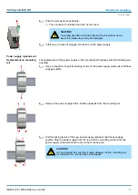
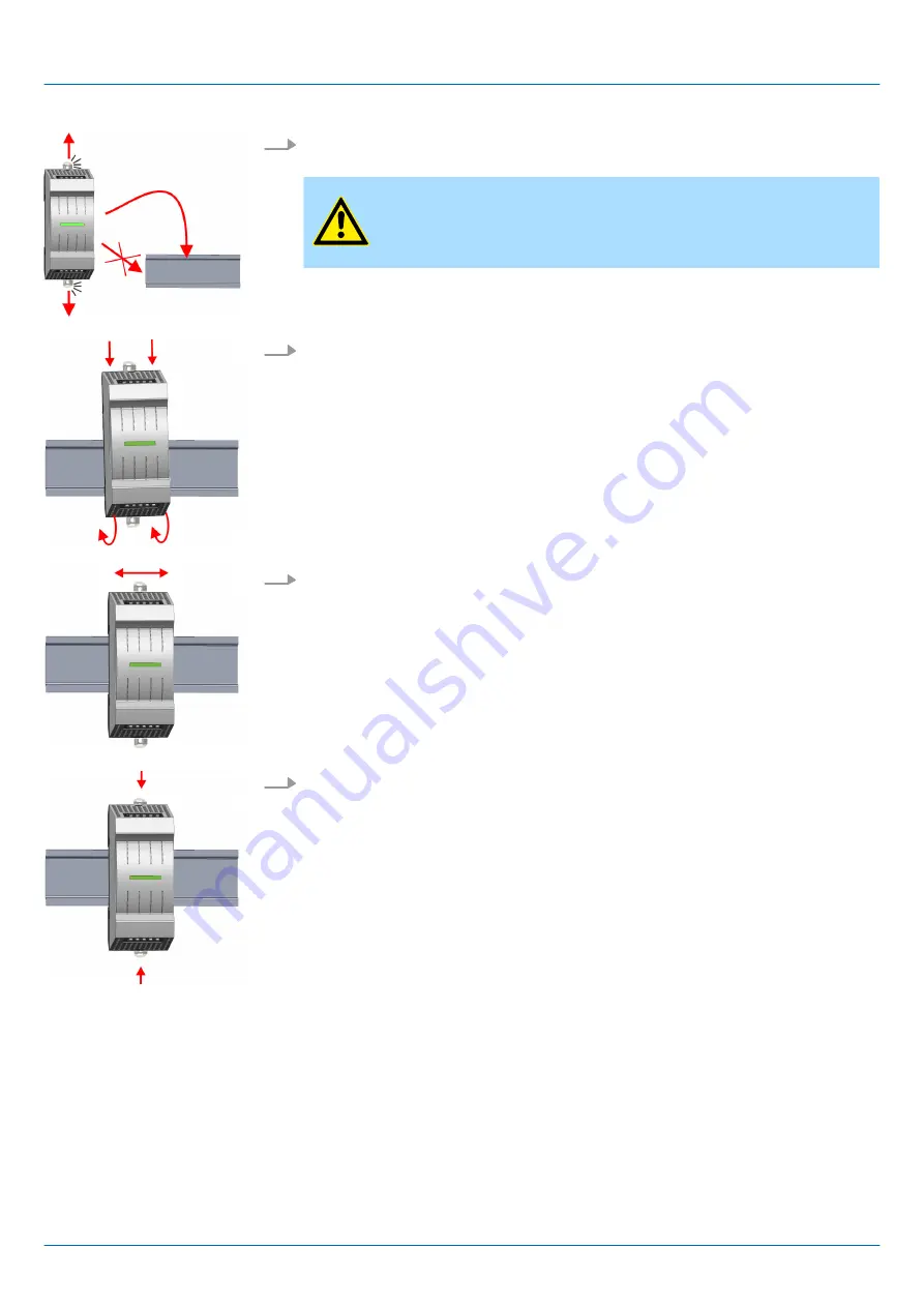
The power supply has a locking lever on the upper and lower side. Pull these levers

outwards as shown in the figure, until these engage audible.

CAUTION!

It is not allowed to mount the module sideways on the mounting rail,

as otherwise the module may be damaged.

3.

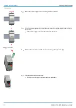
Plug the power supply from the top onto the mounting rail and turn the power supply

downward until it rests on the mounting rail.

4.

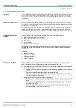
Move the power supply on the mounting rail at its position.

5.

To fix the power supply at the mounting rail, move the locking levers back to the ini-

tial position.

ð

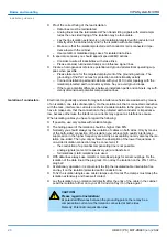
The power supply is now mounted and can be wired.

VIPA System MICRO

Basics and mounting

Mounting > Mounting with mounting rail

HB400 | PS | M07-2BA00 | en | 20-02


14

Summary of Contents for PS M07

Page 1: ...PS M07 2BA00 Manual HB400 PS M07 2BA00 en 20 02 VIPA System MICRO Power supply PS M07...

Page 2: ...M07 2BA00_000_PS M07 1 EN 2020 YASKAWA Europe GmbH Ohmstra e 4 91074 Herzogenaurach Tel 49 9132 744 0 Fax 49 9132 744 186 Email info yaskawa eu com Internet www yaskawa eu com...

Page 3: ...10 2 4 Mounting 12 2 4 1 Mounting without mounting rail 13 2 4 2 Mounting with mounting rail 13 2 5 Wiring 15 2 5 1 Wiring power supply 15 2 6 Demounting 16 2 7 Installation guidelines 19 2 8 General...

Page 4: ...riptions may be included for units which are not present at the customer site The exact scope of delivery is described in the respective purchase contract Hereby YASKAWA Europe GmbH declares that the...

Page 5: ...cumentation HER yaskawa eu com Contact your local representative of YASKAWA Europe GmbH if you encounter problems or have questions regarding the product If such a location is not available you can re...

Page 6: ...e in the manual n An overall table of contents at the beginning of the manual n References with page numbers The manual is available in n printed form on paper n in electronic form as PDF file Adobe A...

Page 7: ...ions DANGER This device is not certified for applications in in explosive environments EX zone The manual must be available to all personnel in the n project design department n installation departmen...

Page 8: ...that have been damaged by electrostatic discharges can fail after a temperature change mechanical shock or changes in the electrical load Only the consequent implementation of protection devices and m...

Page 9: ...ower module for power supply CPU electronic and the I O components are supplied as well as the electronic of the periphery modules which are connected via backplane bus To connect the power supply of...

Page 10: ...r supply By means of up to 8 periphery modules you can extend the internal I O areas The attachment to the CPU is made by plugging them on the right side of the CPU 2 3 Dimensions Dimensions in mm Pow...

Page 11: ...Dimensions in mm Dimensions extension module EM M09 Dimensions power supply VIPA System MICRO Basics and mounting Dimensions HB400 PS M07 2BA00 en 20 02 11...

Page 12: ...ce For operation within the specified nominal values they must comply with a minimum distance of 30 mm on one side of the module Dimensions in mm Dimensions periphery module VIPA System MICRO Basics a...

Page 13: ...e locking levers get visible 2 Use this openings to fix your power supply to your back wall with appropriate screws Consider the installation clearances for the power supply The power supply is now mo...

Page 14: ...maged 3 Plug the power supply from the top onto the mounting rail and turn the power supply downward until it rests on the mounting rail 4 Move the power supply on the mounting rail at its position 5...

Page 15: ...V specification must be separated from the system s equipment 2 5 1 Wiring power supply For wiring the power supply has removable connectors With the wiring of the connectors a push in spring clip tec...

Page 16: ...es the wire 2 Pull the wire from the round hole CAUTION To protect the power supply lines you should use a circuit breaker with the following characteristics Rated current at AC 230V 4A Tripping chara...

Page 17: ...the power supply outwards until these engage audible 2 Remove the power supply with a rotation upwards from the mounting rail 3 Pull the locking levers of the new power supply outwards until these en...

Page 18: ...rs back to the ini tial position The power supply is now mounted and can be wired 1 Remove the connectors which are not necessary at the power supply 2 Plug again the wired connectors Now you can brin...

Page 19: ...the interference cause interferences to your control occur by means of different coupling mechanisms There are n galvanic coupling n capacitive coupling n inductive coupling n radiant coupling In the...

Page 20: ...h conductor is impedance low because otherwise the interference currents may appear as interference cause When isolating cables you have to regard the following n If possible use only cables with isol...

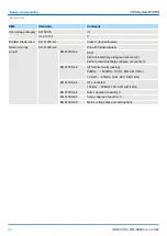
Page 21: ...uts outputs Protective measures against short circuit Environmental conditions to EN 61131 2 Climatic Storage transport EN 60068 2 14 40 80 C Operation Horizontal installation hanging EN 61131 2 0 60...

Page 22: ...e of severity 3 6kV at contact discharge degree of severity 3 EN 61000 4 3 HF field immunity casing 80MHz 1000MHz 10V m 80 AM 1kHz 1 4GHz 6 0GHz 3V m 80 AM 1kHz EN 61000 4 6 HF conducted 150kHz 80MHz...

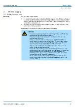
Page 23: ...re you start to work on at the power supply for installation or maintenance you have to disconnect it from the main power source i e the power line is to be switched off unplug the plug with perma nen...

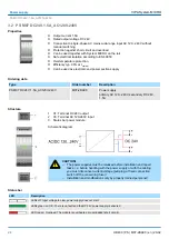
Page 24: ...X1 Terminal DC 24V output 2 X3 Terminal AC 120 240V input 3 Status bar power module Schematic diagram CAUTION The power supplies must be released before installation and repair tasks i e before handl...

Page 25: ...racteristic C So that the circuit breaker can be easily replaced or reset this should be mounted easily accessible The DC 24V output is divided into 2 terminals each Here you can connect your compo ne...

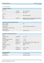
Page 26: ...0 119V 100 119V 120 240V Ambient temperature horizontal installation 0 55 C 0 35 C 0 45 C Ambient temperature vertical installation 0 50 C 0 30 C 0 40 C Output current 1 5A 2A Input voltage DC 110 119...

Page 27: ...e 1 5 A Power supply parallel switchable Protect type short circuits overload Ripple of output voltage max BW 20 MHz 25 mV Efficiency typ 88 Power loss typ 5 W Status information alarms diagnostics St...

Page 28: ...ross weight 170 g Environmental conditions Operating temperature 0 C to 60 C Storage temperature 40 C to 80 C Certifications UL certification yes KC certification in preparation VIPA System MICRO Powe...

Page 29: ...Appendix VIPA System MICRO Appendix HB400 PS M07 2BA00 en 20 02 29...

Page 30: ...Content A History of changes 31 VIPA System MICRO Appendix HB400 PS M07 2BA00 en 20 02 30...

Page 31: ...A History of changes Rev Changes 20 02 The manual was created VIPA System MICRO History of changes HB400 PS M07 2BA00 en 20 02 31...

Reviews: