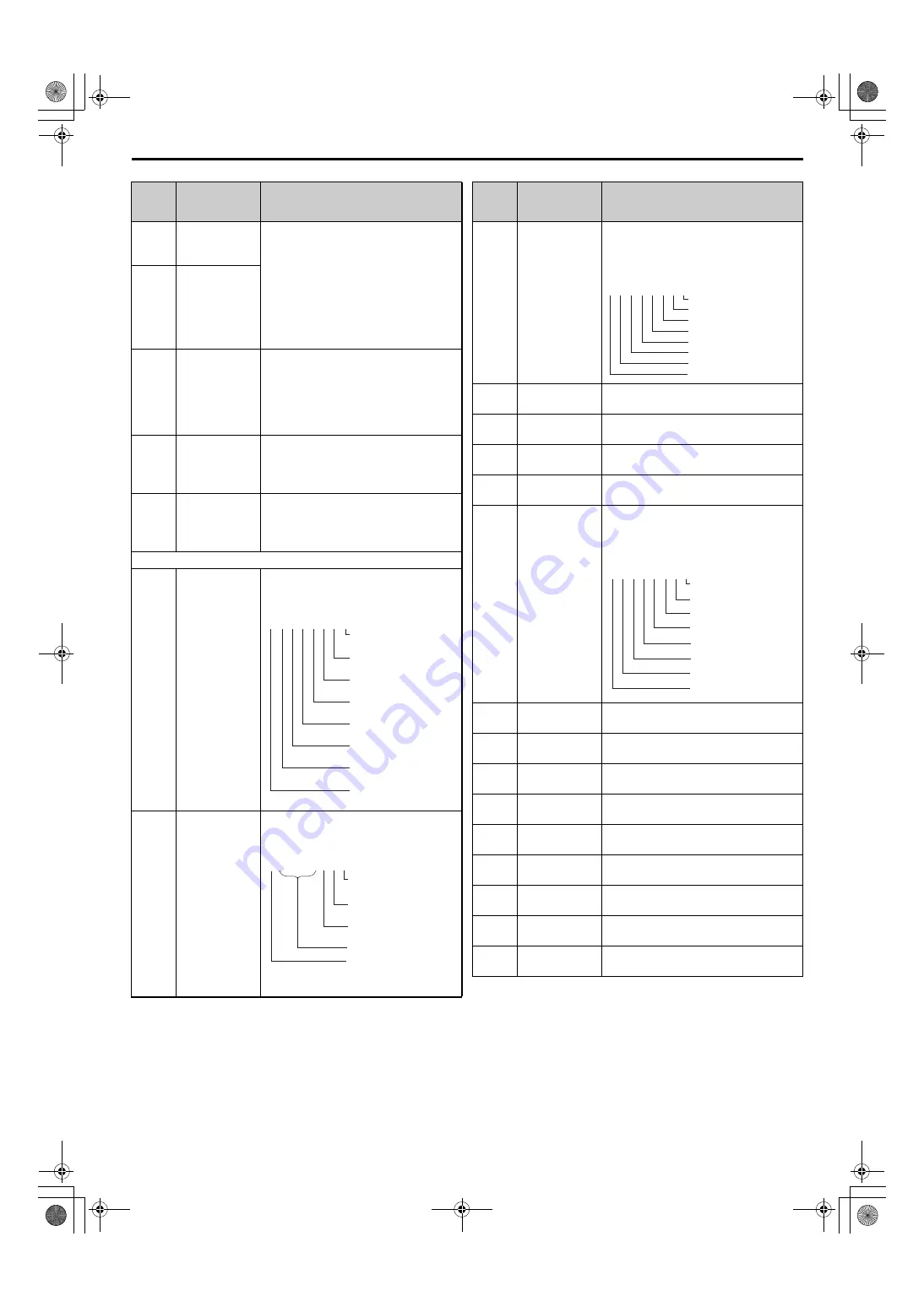
7 Parameter Table
YASKAWA ELECTRIC
TOEP C710656 09D YASKAWA Power Regenerative Unit - R1000 Quick Start Guide
27
L8-66
(670H)
Power Supply
Fault Detection
Voltage Level
There is normally no need to change this
parameter from the default value. The
main circuit DC voltage ripple is
monitored in a cycle of 200 ms. If the
difference between the maximum and
minimum values of the ripple exceeds the
value that is set in L8-66 for the number of
times that is set in L8-67, a power supply
fault is detected.
L8-67
(671H)
Number of
Times of Power
Supply Fault for
Detection
L8-69
(673H)
Input Phase Loss
Protection
Selection 3
Sets whether to enable or disable the
protective function for the regenerative
unit when there is an input phase loss.
0: Disabled
1: Enabled (Detect input phase loss and
power supply imbalance.)
L9-08
DC5 Conveter
Unit
Replacement
Selection
0: Disable
1: Enable
L9-09
DC3 Conveter
Unit
Replacement
Selection
0: Disable
1: Enable
U1: Operation Status Monitors
U1-10
(49H)
Input Terminal
Status
Displays the input terminal status.
U1-11
(4AH)
Output Terminal
Status
Displays the output terminal status.
No.
(Addr.
Hex)
Name
Description
U1 - 10=
0 0 0 0 0 0 0 0
Digital input 1
(terminal S1 enabled)
Digital input 2
(terminal S2 enabled)
Digital input 3
(terminal S3 enabled)
Digital input 4
(terminal S4 enabled)
Digital input 5
(terminal S5 enabled)
Digital input 6
(terminal S6 enabled)
Digital input 7
(terminal S7 enabled)
Digital input 8
(terminal S8 enabled)
1: ON 0: OFF
U1 - 11=
0 0 0 0 0 0 0 0
Multi-Function Relay
Output (terminal M1-M2)
Multi-Function Relay
Output (terminal M3-M4)
Multi-Function Relay
Output (terminal M5-M6)
Reserved
Fault Relay
(terminal MA/MB-MC
closed MA/MB-MC open)
1: ON 0: OFF
U1-12
(4BH)
Drive Status
Verifies the regenerative unit operation
status.
U1-13
(4EH)
Terminal A1
Input Level
Displays the signal level to analog input
terminal A1.
U1-14
(4FH)
Terminal A2
Input Level
Displays the signal level to analog input
terminal A2.
U1-15
(50H)
Terminal A3
Input Level
Displays the signal level to analog input
terminal A3.
U1-18
(61H)
oPE Fault
Parameter
Displays the parameter number that caused
the oPE02 or oPE08 operation error.
U1-19
(66H)
MEMOBUS/
Modbus Error
Code
Displays the contents of a MEMOBUS/
Modbus error.
U1-25
(4DH)
Software
Number (Flash)
FLASH ID
U1-26
(5BH)
Software No.
(ROM)
ROM ID
U1-27
(7A8H)
Message ID
(OPR)
Shows the message ID number for OPE.
U1-28
(7A9H)
Message ID
(INV)
Shows the message ID number for INV.
U1-52
(1081H)
DC Bus Voltage
Feedback
Shows the DC bus voltage feedback value.
U1-54
(1083H)
Power Supply
Voltage
Shows the power supply voltage.
U1-55
(1084H)
Power Supply
Current
Shows the current on the power supply
side.
U1-57
(1086H)
Power Supply
Side Power
Shows the power on the power supply
side.
U1-58
(1087H)
Power Supply
Frequency
Shows the frequency on the power supply
side.
No.
(Addr.
Hex)
Name
Description
U1 - 12=
0 0 0 0 0 0 0 0
Bit 0: During run
Bit 1: Not used
Bit 2: Not used
Bit 3: During fault reset signal input
Bit 4: During voltage agree
Bit 5: Operation ready
Bit 6: Alarm
Bit 7: Fault
U1 - 19=
0 0 0 0 0 0 0 0
CRC Error
Data Length Error
Not Used
Parity Error
Overrun Error
Framing Error
Timed Out
Not Used
1
1
0
1
1
1
1
0
D1000R1000_QSG_E_conditional.book 27 ページ 2018年2月26日 月曜日 午後2時38分


