3 Wiring and Connection
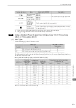
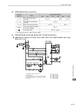
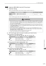
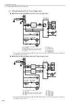
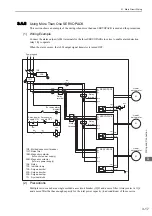
3.1.4 Using the SERVOPACK with Single-phase, 200-V Power Input
3-14
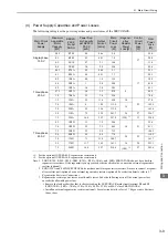
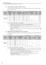
(5) Power Supply Capacities and Power Losses
The following table shows SERVOPACK’s power supply capacities and power losses when using a single-
phase 200 V power supply.
∗
The official model name is SGDV-120AE5A008000.
Note 1. SGDV-R70A, R90A, 1R6A, and 2R8A SERVOPACKs do not have built-in regenerative resistors. If the regener-
ative energy exceeds the specified value, connect an external regenerative resistor.
2. Regenerative resistor power losses are allowable losses. Take the following action if the actual power losses
exceeds the allowable power loss.
• Remove the wire connecting terminals B2 and B3 of the SERVOPACK main circuit terminals or remove the
short bar (SGDV-5R5A,120A).
• Install an external regenerative resistor between the external regenerative resistor connection terminals B1/
and B2
3. External regenerative resistors are options.
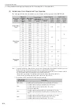
(6) Molded-case Circuit Breaker and Fuse Capacities
The following table shows the molded-case circuit breaker and fuse capacities when using single-phase 200 V
power supply.
∗
The official model name is SGDV-120AE5A008000.
Note 1. To comply with the low voltage directive, connect a fuse to the input side. Select the fuse for the input side from
among models that are compliant with UL standards.
The table above also provides the net values of current capacity and inrush current. Select a fuse and a molded-
case circuit breaker which meet the breaking characteristics shown below.
• Main circuit, control circuit: No breaking at three times the current values shown in the table for 5 s.
• Inrush current: No breaking at the current values shown in the table for 20 ms.
2. The following usage restrictions apply to the UL installation certification conditions for the SGDV-
120AE5A008000 SERVOPACK.
Available rated current for molded-case circuit breaker: 40 A or less.
Main Power
Supply
Maximum
Applicable
Servomotor
Capacity
[kW]
SERVOPACK
Model
SGDV-
Power Supply
Capacity per
SERVOPACK
[kVA]
Output
Current
[Arms]
Main Circuit
Power Loss
[W]
Regenerative
Resistor
Power Loss
[W]
Control
Circuit
Power Loss
[W]
Total
Power
Loss
[W]
Single-phase,
200 V
0.05
R70A 0.2
0.66
5.2
–
17
22.2
0.1
R90A 0.3
0.91
7.4
24.4
0.2
1R6A 0.7
1.6
13.7
30.7
0.4
2R8A
1.2
2.8
24.9
41.9
0.75
5R5A
1.9
5.5
52.7
8
77.7
1.5
120A
*
4
11.6
68.2
10
22
100.2
Main Power
Supply
Maximum
Applicable
Servomotor
Capacity
[kW]
SERVOPACK
Model
SGDV-
Power Supply
Capacity per
SERVOPACK
[kVA]
Current Capacity
Inrush Current
Main Circuit
[Arms]
Control
Circuit
[Arms]
Main Circuit
[A0-p]
Control
Circuit
[A0-p]
Single-phase,
200 V
0.05
R70A 0.2
2
0.2
33
70
0.1
R90A 0.3
2
0.2
1R6A 0.7
3
0.4
2R8A
1.2
5
0.75
5R5A
1.9
9
33
1.5
120A
*
4
16
0.25

