3.1 Main Circuit Wiring
3-15
3
Wiring and Connection
3.1.5
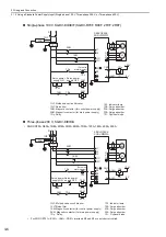
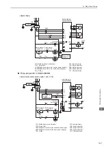
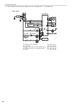
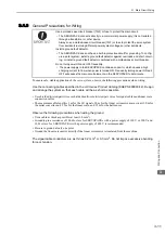
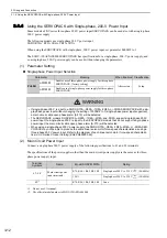
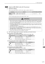
Using the SERVOPACK with a DC Power Input
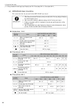
(1) Parameter Settings
When using the SERVOPACK with a DC power input, set parameter Pn001.2 to 1.
Observe the following precautions when using a DC power input.
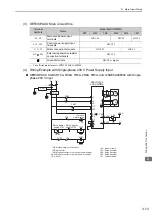
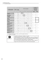
(2) DC Power Supply Input Terminals for the Main and Control Circuits
Three-phase, 200-V SGDV-
A
(
= R70, R90, 1R6, 2R8, 3R8, 5R5, 7R6, 120, 180, 200, 330)
Three-phase, 200-V SGDV-
A (
= 550)
Three-phase, 400-V SGDV-
D
(
= 1R9, 3R5, 5R4, 8R4, 120, 170, 260)
Parameter
Meaning
When Enabled Classification
Pn001
n.
0
Enables use of AC power input.
After restart
Setup
n.
1
Enables use of DC power input.
WARNING
• Either AC or DC power can be input to the 200 V, 400 V SERVOPACKs. Always set Pn001.2 to 1 to spec-
ify a DC power input before inputting DC power. Only AC power can be input to the 100 V SERVOPACKs.
If DC power is input without changing the parameter setting, the SERVOPACK’s internal elements will burn and
may cause fire or equipment damage.
• With a DC power input, time is required to discharge electricity after the main power supply is turned OFF.
A high residual voltage may remain in the SERVOPACK after the power supply is turned OFF. Be careful
not to get an electric shock.
• Install fuses on the wires if DC power is used.
• Linear servomotor returns a regenerated energy to the power supply. The SERVOPACK that can use a
DC power supply is not capable of processing the regenerated energy. Provide measures to process the
regenerated energy on the power supply.
• With a DC power input, connect an external inrush current limit circuit.
Failure to observe this caution may result in damage to the product.
Terminal Symbols
Name
Specification
B1/
Main circuit plus terminal
270 to 320 VDC
2
Main circuit minus terminal
0 VDC
L1C, L2C
Control power supply input terminal
200 to 230 VAC
Terminal Symbols
Name
Specification
B1/
Main circuit plus terminal
270 to 320 VDC
Main circuit minus terminal
0 VDC
L1C, L2C
Control power supply input terminal
200 to 230 VAC
Terminal Symbols
Name
Specification
B1/
Main circuit plus terminal
513 to 648 VDC
2
Main circuit minus terminal
0 VDC
24 V, 0 V
Control power supply input terminal
24 VDC (
±
15%)

