7.3 Operation in Parameter Setting Mode (Pn
)
7-23
7
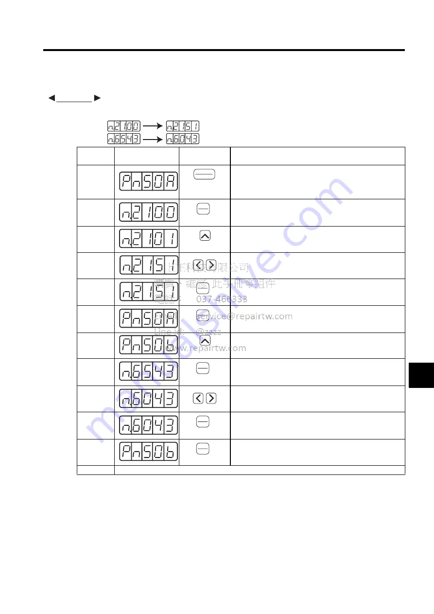
(3) Allocating Input Signals
The procedure to replace Servo ON (/S-ON) signal allocated to CN1-14 and Forward External Torque Limit
(/P-CL) allocated to CN1-11 is shown below.
Step
Display after
Operation
Key
Description
1
Press the DSPL/SET Key to select the “value setting parameter”
mode. If a parameter other than Pn50A is displayed, press the
UP or DOWN Key to set Pn50A.
Note: The enabled digit blinks.
2
Press the DATA/ENTER Key to display the current data of
Pn50A.
(/S-ON is allocated to CN1-14.)
3
Press the UP Key to set to “1.”
(Sequence input signals can be freely set.)
4
Press the LEFT or RIGHT Key to select the second digit from
the right. Press the UP key to set to “5.”
(Changes the allocation of /S-ON from CN1-14 to CN1-11.)
5
Press the DATA/ENTER Key. The value blinks and is saved.
At the moment, the CN1-11 operates with OR logic for
/S-ON and /P-CL.
6
Press the DATA/ENTER Key to return to the display Pn50A.
7
Press the UP Key to set Pn50B.
Note: The enabled digit blinks.
8
Press the DATA/ENTER Key to display the current data of
Pn50B.
(/P-CL is allocated to CN1-11.)
9
Press the LEFT or RIGHT Key to select the third digit from the
right. Press the DOWN Key to set to “0.”
(Changes the allocation of /P-CL from CN1-11 to CN1-40.)
10
Press the DATA/ENTER Key. The value blinks and is saved.
11
Press the DATA/ENTER Key to return to the display Pn50B.
/S-ON is allocation to CN1-11, and /P-CL is allocated to CN1-
14.
12
Turn the power OFF and ON again to enable the change of input signal selections (Pn50A and Pn50B).
EXAMPLE
Pn50B:
Pn50A:
Before
After
DSPL
SET
(DSPL/SET Key)
DATA
ENTER
(DATA/ENTER
Key)
(UP Key)
DATA
ENTER
(DATA/ENTER
Key)
DATA
ENTER
(DATA/ENTER
Key)
(UP Key)
DATA
ENTER
(DATA/ENTER
Key)
DATA
ENTER
(DATA/ENTER
Key)
DATA
ENTER
(DATA/ENTER
Key)
Summary of Contents for SGDJ Series
Page 19: ...xix INDEX Revision History ...
Page 34: ...2 Selections 2 8 2 4 Selecting Cables CN4 c d e FG ...
Page 176: ...8 3 8 ...


