8.6 Operating Using Position Control
8-53
8
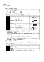
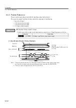
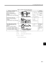
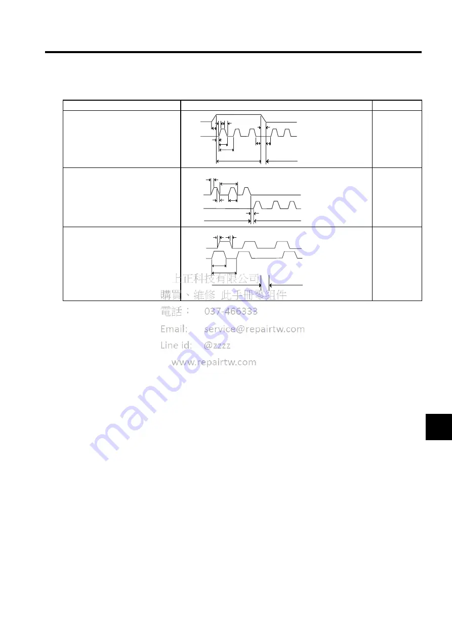
Table 8.1 Reference Pulse Input Signal Timing
Reference Pulse Signal Form
Electrical Specifications
Remarks
Sign and pulse train input
(SIGN and PULS signal)
Maximum reference frequency:
500 kpps
(For open-collector output: 200 kpps)
t1
,
t2
≤
0.1 ms
t3
,
t7
≤
0.1 ms
t4
,
t5
,
t6
>
3
µ
s
τ
≥
1.0
µ
s
(
τ
/T)
×
100
≤
50%
Sign (SIGN)
H = Forward
reference
L = Reverse
reference
CW pulse and CCW pulse
Maximum reference frequency:
500 kpps
(For open-collector output: 200 kpps)
t1
,
t2
≤
0.1 ms
t3
>
3
µ
s
τ
≥
1.0
µ
s
(
τ
/T)
×
100
≤
50%
−
Two-phase pulse train with 90
°
phase differential (phase A and
phase B)
Maximum reference frequency
×
1 input pulse multiplier: 500 kpps
×
2 input pulse multiplier: 400 kpps
×
4 input pulse multiplier: 200 kpps
t1
,
t2
≤
0.1 ms
τ
≥
1.0
µ
s
(
τ
/T)
×
100 = 50%
Switching of
the input pulse
multiplier
mode is done
with parameter
Pn200.0 set-
ting.
Forward
reference
Reverse
reference
t1 t2
t3
t4
t5
t6
t7
T
τ
SIGN
PULS
Forward
reference
Reverse
reference
t2
t3
T
τ
CW
CCW
t1
Phase B leads
phase A by 90
°
Phase B lags
phase A by 90
°
Forward reference
Reverse reference
Phase B
Phase A
t2
τ
T
t1
Summary of Contents for SGDJ Series
Page 19: ...xix INDEX Revision History ...
Page 34: ...2 Selections 2 8 2 4 Selecting Cables CN4 c d e FG ...
Page 176: ...8 3 8 ...


