background image

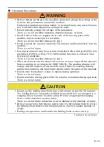
• Before starting operation with a machine connected, change the settings of the 

switches and parameters to match the machine.

• Do not radically change the settings of the parameters.

• Install limit switches or stoppers at the ends of the moving parts of the 

machine to prevent unexpected accidents.

• For trial operation, securely mount the Servomotor and disconnect it from the 

machine.

• Forcing the motor to stop for overtravel is disabled when the Jog (Fn002), Ori-

gin Search (Fn003), or Easy FFT (Fn206) utility function is executed. Take 

necessary precautions.

• When an alarm occurs, the motor will coast to a stop or stop with the dynamic 

brake according to a setting in the SERVOPACK. The coasting distance will 

change with the moment of inertia of the load. Check the coasting distance 

during trial operation and implement suitable safety measures on the machine.

• Do not enter the machine’s range of motion during operation.

• Do not touch the moving parts of the Servomotor or machine during operation.


E-11

Operation Precautions

WARNING

Unexpected machine operation, failure, or personal injury may occur if opera-

tion is started before appropriate settings are made.

There is a risk of unstable operation, machine damage, or injury.

There is a risk of machine damage or injury.

There is a risk of injury.

There is a risk of machine damage or injury.

There is a risk of injury.

There is a risk of injury.


CAUTION

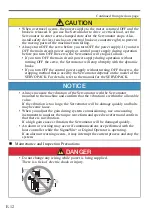
• Do not use the holding brake built into a Servomotor to stop the Servomotor. 

The holding brake is designed to hold the motor shaft. It is not designed as a 

stopping device to ensure machine safety. Provide an appropriate stopping 

device on the machine to ensure safety.

There is a risk of brake failure due to wear, damage to the machine, or injury.

• Before you operate a Servomotor, supply power to the holding brake to release 

the holding brake. Refer to the timing charts in your Servomotor manual for 

details.

• During trial operation, confirm that the holding brake works correctly.

Continued on next page.

Summary of Contents for SGM series

Page 1: ...Servo Drive Safety Precautions MANUAL NO TOEP C230260 00A Type SGM To properly use the product read this manual thoroughly and retain for easy reference inspection and maintenance Ensure the end user...

Page 2: ...liability is assumed with respect to the use of the information contained herein Moreover because Yaskawa is constantly striving to improve its high quality products the information contained in this...

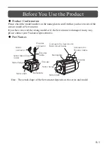
Page 3: ...or if the Servomotor is damaged in any way please contact your Yaskawa representative Part Names Note The actual shape of the Servomotor depends on the series and model Motor flange Nameplate Connect...

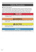
Page 4: ...icates precautions that if not heeded could result in property damage Safety Information To prevent personal injury and equipment damage in advance the following signal words are used to indicate safe...

Page 5: ...tors and other components can be very hot while power is ON or soon after the power is turned OFF Implement safety measures such as installing covers so that hands and parts such as cables do not come...

Page 6: ...wer supply and Servomotor The time required for a holding brake to operate depends on the types of pro tective devices The time required for a holding brake to operate will also change if holding brak...

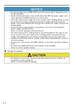
Page 7: ...transportation Follow all instructions on the packages E 5 Transportation Precautions NOTICE Locations that are subject to direct sunlight Locations that are subject to ambient temperatures that exce...

Page 8: ...n machines are packed with fumigated wooden materials the elec trical components may be greatly damaged by the gases or fumes resulting from the fumigation process In particular disinfectants containi...

Page 9: ...nsation as the result of extreme changes in temperature Locations that are subject to corrosive or flammable gases Locations that are near flammable materials Locations that are subject to dust salts...

Page 10: ...tions on the installation orientation Refer to the relevant technical documents If an installation orientation is specified for a Servomotor with a Gear install the Servomotor in the specified orienta...

Page 11: ...t circuits may cause short circuit failures If a short circuit failure occurs as a result of any of these causes the holding brake will not work This could damage the machine or cause an accident that...

Page 12: ...or Encoder Cables together or run them through the same duct If you do not place power lines and low current lines in sepa rate ducts separate them by at least 30 cm For a motor with a cooling fan ch...

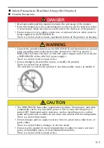
Page 13: ...during operation Do not touch the moving parts of the Servomotor or machine during operation E 11 Operation Precautions WARNING Unexpected machine operation failure or personal injury may occur if ope...

Page 14: ...a measuring instrument to monitor the torque waveform and speed waveform and confirm that there is no vibration An alarm or warning may occur if communications are performed with the host controller...

Page 15: ...art opera tion If the Servo ON signal is input to the SERVOPACK and an alarm is reset the Servomotor may suddenly restart operation Confirm that the servo is OFF and ensure safety before you reset an...

Page 16: ...duct in any way Yaskawa disavows any responsibil ity for damages or losses that are caused by modified products E 14 Disposal Precautions General Precautions Warranty Details of Warranty Warranty Peri...

Page 17: ...am execution of the programs provided by the user or by a third party for use with programmable Yaskawa products The information described in product catalogs or manuals is provided for the pur pose o...

Page 18: ...property Systems that require a high degree of reliability such as systems that supply gas water or electricity or systems that operate continuously 24 hours a day Other systems that require a similar...

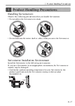
Page 19: ...onto the motor shaft or cables when you move the Servomotor Servomotor Installation Environment Install the Servomotor in the following environments If you use a Servomotor in an inappropriate enviro...

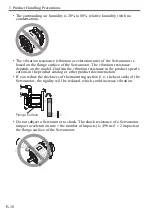
Page 20: ...he model Confirm the vibration resistance in the product specifi cations in the product catalog or other product documentation If you reduce the thickness of the mounting section i e the heat sink of...

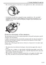
Page 21: ...tor Confirm the protection class of your Servomotor in the Servomotor manual or catalog or on Yaskawa s product and technical information website http www emechatronics com Observe the following preca...

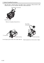
Page 22: ...tors shown below with dotted circle on Servomotors that have cables attached Shaft opening Specified connectors Medium Capacity Servomotors Connectors Shaft opening Small Capacity Servomotors with Cab...

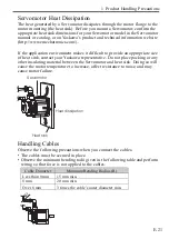
Page 23: ...ate size of heat sink contact your Yaskawa representative Do not place packing or any other insulating material between the Servomotor and heat sink Doing so will cause the motor temperature to increa...

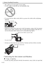
Page 24: ...ervomotor connect the Servomotor Main Circuit Cable connector first in the following figure and then con nect the Encoder Cable connector in the following figure Always use the connectors specified by...

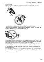
Page 25: ...the coupling depends on the speed of the motor and the type of the coupling center the coupling within 0 03 mm Also refer to the coupling catalog for manufacturer requirements Even within this range...

Page 26: ...fts and make adjustments so that it does not catch Using a Belt Select a belt that is suitable for the allowable radial load and output of the Ser vomotor When the Servomotor accelerates or decelerate...

Page 27: ...ing is not subject to oil mist use a standard Servomotor The operating conditions for a Servomotor with an Oil Seal are given below Note The oil seal is a single lip spring loaded oil seal made of nit...

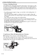
Page 28: ...rvomotor model as given in the manual and prod uct catalog Also confirm the input voltage to the holding brake Always install a surge absorber in a protective circuit between the brake power supply an...

Page 29: ...even when power is not being supplied to the holding brake This results in a certain amount of rotational play in the motor output shaft Amount of play 1 5 max initial value Braking Noise from Servomo...

Page 30: ...med only by qualified engineers Contact your Yaskawa representative for help with failures repairs or part replacement CAUTION If there is any main circuit voltage left the risk of electric shock stil...

Page 31: ...s power line and FG The insulation is normal if the resistance is 10 M or higher If the resistance is less than 10 M contact your Yaskawa representative Replace the oil seal At least once every 5 000...

Page 32: ...in the table are only for reference The actual service lives will depend on the application conditions and environment Part Standard Ser vice Life Remarks Bearings 20 000 hours The service life is aff...

Page 33: ...ion Rev No Section Revised Content September 2015 4 Back cover Revision Address April 2015 3 Front cover back cover Revision Format October 2014 2 Back cover Revision Address August 2014 1 Japanese ve...

Page 34: ...E 32...
Page 35: ...iland Phone 66 2 017 0099 Fax 66 2 017 0799 http www yaskawa co th YASKAWA ELECTRIC CHINA CO LTD 22F One Corporate Avenue No 222 Hubin Road Shanghai 200021 China Phone 86 21 5385 2200 Fax 86 21 5385 3...

Reviews: