4.4 Command Option Attachable-type FT82 SERVOPACKs with INDEXER Modules
4-137
4
Parameter Li
s
t
s
*1.
Refer to the following manual for details.
Σ
-7-Series
Σ
-7S SERVOPACK Command Option Attachable Type with INDEXER Module Product Manual
(Manual No.: SIEP S800001 64)
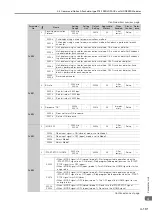
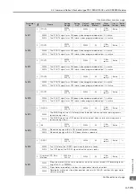
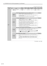
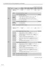
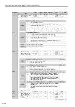
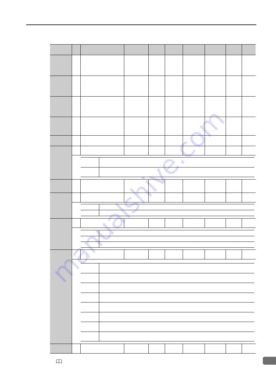
PnB33
4
Origin Return Moving
Speed
1 to
99999999
*16
1000
Refer-
ence
units/
min
1000
All
Immedi-
ately
Setup
*1
PnB35
4
Origin Return Approach
Speed
1 to
99999999
*16
1000
Refer-
ence
units/
min
1000
All
Immedi-
ately
Setup
*1
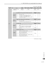
PnB37
4
Origin Return Creep
Speed
1 to
99999999
*16
1000
Refer-
ence
units/
min
1000
All
Immedi-
ately
Setup
*1
PnB39
4
Origin Return Final
Move Distance
-99999999
to
+99999999
*16
1 refer-
ence
unit
0
All
Immedi-
ately
Setup
*1
PnB3B to
PnB4D
4
Reserved parameters
(Do not change.)
–
–
0
All
–
Setup
–
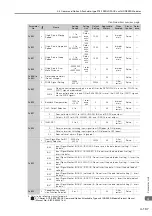
PnB4F
2
ZONE Signal Setting
0000h,
0001h
–
0000h
All
After
restart
Setup
*1
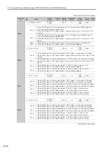
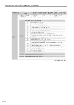
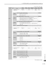
PnB50
2
Backlash Compensation
-1000 to
+1000
1 refer-
ence
unit
0
All
Immedi-
ately
Setup
*1
PnB51
2
/ALO Output Selection
0 to 1
–
0
All
After
restart
Setup
*1
PnB52
2
/ALM-RST
0 to 3
–
0
All
After
restart
Setup
*1
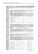
PnB53
2
Input Signal Monitor IN1
Polarity Selection
0000h to
00FFh
–
0050h
All
After
restart
Setup
–
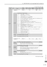
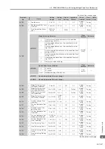
PnB54
2
Speed/Position Expan-
sion Function Selection
0 or 1
–
0
All
After
restart
Setup
–
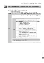
Continued from previous page.
Parameter
No.
Size
Name
Setting
Range
Setting
Unit
Default
Setting
Applicable
Motors
When
Enabled
Classi-
fication
Refer-
ence
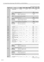
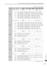
0000h
When the control power supply is turned ON or the SERVOPACK is reset, the /POUT0 to /
POUT7 signals are disabled.
0001h
When control power is turned ON or SERVOPACK is reset, the /POUT0 to /POUT7 signals
are the ZONE signals.
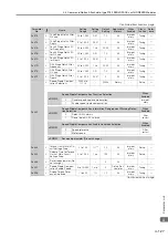
0
Does not output /ALO1 to /ALO3. (/WARN, /BK, and /S-RDY are output.)
1
Outputs /ALO1 to /ALO3. (/WARN, /BK, and /S-RDY are not output.)
0
Resets alarms by switching input signal from OFF (open) to ON (closed).
1
Resets alarms by switching input signal from ON (closed) to OFF (open).
2, 3
Does not reset alarms. (Signal is ignored.)
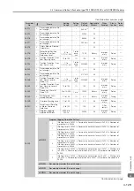
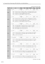
Bit 0
Input Signal Monitor IN1 Bit 0 (/SVON) (0: Do not invert the data (default setting), 1: Invert
the data.)
Bit 1
Input Signal Monitor IN1 Bit 1 (/ALM-RST) (0: Do not invert the data (default setting), 1:
Invert the data.)
Bit 2
Input Signal Monitor IN1 Bit 2 (/P-OT) (0: Do not invert the data (default setting), 1: Invert the
data.)
Bit 3
Input Signal Monitor IN1 Bit 3 (/N-OT) (0: Do not invert the data (default setting), 1: Invert the
data.)
Bit 4
Input Signal Monitor IN1 Bit 4 (/DEC) (0: Do not invert the data, 1: Invert the data (default
setting).)
Bit 5
Input Signal Monitor IN1 Bit 5 (not used) (0: Do not invert the data (default setting), 1: Invert
the data.)
Bit 6
Input Signal Monitor IN1 Bit 6 (/RGRT) (0: Do not invert the data, 1: Invert the data (default
setting).)
Bit 7
Input Signal Monitor IN1 Bit 7 (not used) (0: Do not invert the data (default setting), 1: Invert
the data.)


