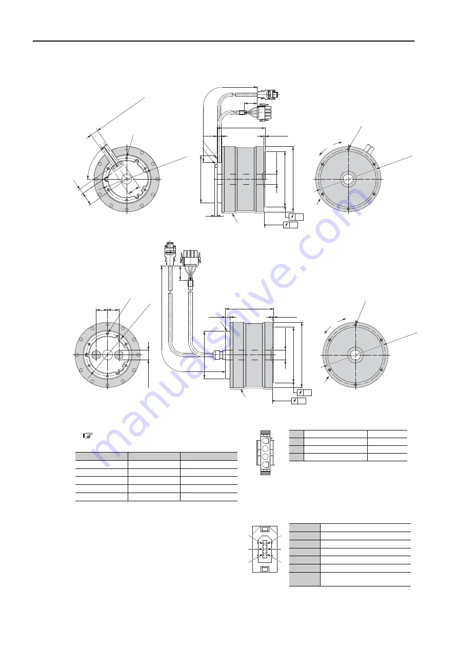
3.3 External Dimensions
3-22
SGM7D-08G, -18G. -24G, -34G, and -45G
•
Servomotors with the Cable on the Bottom
•
Servomotors with the Cable on the Bottom
*1.
The shaded section indicates the rotating parts.
*2.
The precision depends on the option specifica-
tion. Refer to the following section for details.
Note: Values in parentheses are reference dimensions.
Connector Specifications
•
Servomotor Connector
Models
•
Plug: 350779-1
•
Pins: 350218-3 or 350547-3 (No.1 to 3)
•
Ground pin: 350654-1 or 350669-1 (No. 4)
Manufacturer: Tyco Electronics Japan G.K.
Mating Connector
•
Cap: 350780-1
•
Socket: 350536-3 or 350550-3
•
Encoder Connector
*
Only absolute-value models with multiturn data.
Model:
55102-0600
Manufacturer: Molex Japan LLC
Mating connector:
54280-0609
Unit: mm
CW
direction
CCW
direction
*1
146 ±
0.2 dia.
6 × M6 × 8
(Divided into equal
sections at 60°.)
L
3 ±0.2
11.5
+2
0
160 dia.
136 dia.
-0.02 -0.06
116 dia.
-0.02 -0.05
(6)
Coated surface
(13)
(32)
55
°
(30)
104 ±0.2 dia.
Cable r
ecess
width: 20, Depth: 100
6 × M6 × 8
(Divided into equal
sections at 60°.)
Fixed part
Cable tie
*2
*2
-0.02
0
25 dia. hole
300 ±50
(35)
Unit: mm
(21.1 dia.)
104 ±0.2 dia.
6 × M6 × 8
(Divided into equal
sections at 60°.)
(28) (28)
160 dia.
136 dia.
-0.02 -0.06
Coated surface
L
3 ±0.2
11.5
+2
0
Fixed part
116 dia.
-0.02 -0.05
*2
*2
CCW
direction
CW
direction
6 × M6 × 8
(Divided into equal
sections at 60°.)
146 ±0.2 dia.
*1
+0.5
0
25 dia. hole
300 ±50
(35)
Model SGM7D-
L
Approx. Mass [kg]
08G
C
92.5 ±1
5.5
18G
C
118 ±1
7.5
24G
C
143 ±1
9.5
34G
C
168 ±1
12
45G
C
194 ±1
14
1
2
3
4
1
Phase U
Red
2
Phase V
Gray
3
Phase W
Blue
4
FG (frame ground)
Green (yellow)
4
2
6
3
1
5
1
PG5V
2
PG0V
3
*
BAT
4
*
BAT0
5
PS
6
/PS
Connector
case
FG
(frame ground)


