6 SynqNet™ Communications
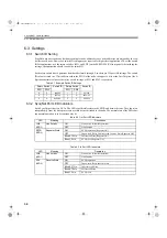
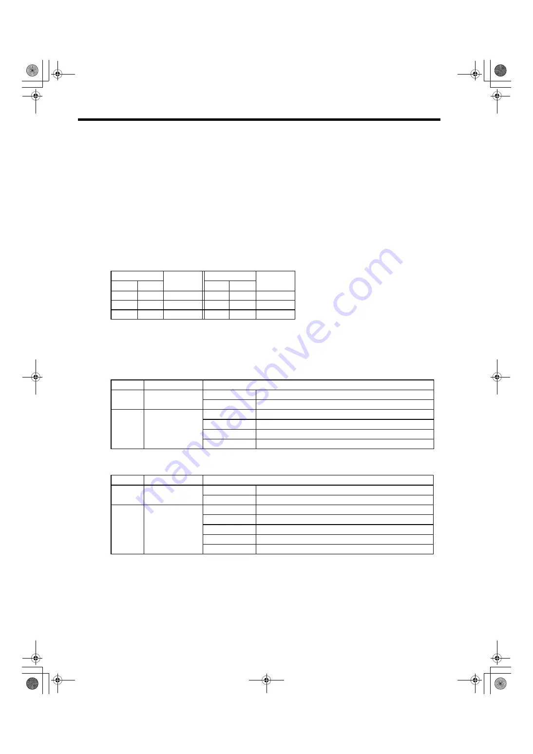
6.3.1 Switch ID Setting
6-8
6.3 Settings
6.3.1 Switch ID Setting
SynqNet does not require any hardware setting for node address because node addresses are assigned by the con-
troller to each node. However, a switch ID setting may be required for higher level applications. To set the switch
ID for applications, use the rotary switches (SW1 and SW2) on the SERVOPACK’s front panel. After making the
settings, the application should re-read the switch ID.
Each rotary switch has 16 positions from hexadecimal 0 through F, so there are 256 possible settings. The switch
ID value is stored in a 32-bit address within the FPGA of the node; the upper 16 bits or the first 2 digits of the 4-
digit hexadecimal value are the rotary switch settings of SW1 and SW2, respectively.
6.3.2 SynqNet Port LED Indicators
Each SynqNet port has two LEDs. The LEDs specifically relate to the FPGA and network states. They function
independently from the drive processors or other devices attached to the node. The normal state of the LEDs dur-
ing normal operation is to be continuously lit.
Table 6.1 Example Switch ID Settings
Rotary Switch
Switch ID
Rotary Switch
Switch ID
SW1
SW2
SW1
SW2
0
0
0x00##
1
2
0x12##
0
1
0x01##
9
A
0x9A##
0
A
0x0A##
F
F
0xFF##
Table 6.2 Out Port LED Indicators
LED
Meaning
Description
LNK
(LED 3)
Link Activity
ON
Link Active (Normal Operation)
OFF
Link Inactive
RPTR
(LED 4)
Repeater State
ON
SYNQ operation [Repeater ON]
OFF
Unpowered, Reset, Undiscovered, Inactive State, Repeater OFF
Blink 0.75 Hz
Discovered State [Repeater ON]
Blink 1.5 Hz
SYNQ Lost [Repeater ON]
Table 6.3 In Port LED Indicators
LED
Meaning
Description
LNK
(LED 1)
Link Activity
ON
Link Active (Normal Operation)
OFF
Link Inactive
RCV
(LED 2)
Receive State
ON
SYNQ operation
OFF
Unpowered, Reset, Inactive State
Blink 0.37 Hz
Undiscovered State
Blink 0.75 Hz
Discovered State
Blink 1.5 Hz
SYNQ Lost
SIEPS80000025.book 8 ページ 2004年10月25日 月曜日 午前11時57分

