4.4 Peripheral Devices
4-11
4
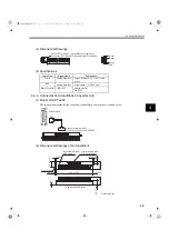
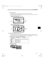
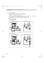
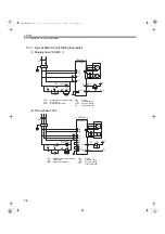
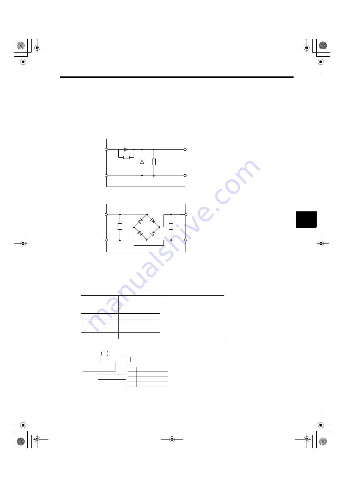
(4) Internal Circuits
Open or close the circuit for the brake’s power supply so that is switched on the AC side.
When switching on the DC side, install a surge protector near the brake coil to prevent damage to the brake coil
from voltage surges due to DC-side switching.
(a) Internal Circuit for 200 VAC
Brake Power Supply Model: LPSE-2H01
(b) Internal Circuit for 100 VAC
Brake Power Supply Model: LPDE-1H01
4.4.6 External Regenerative Resistor
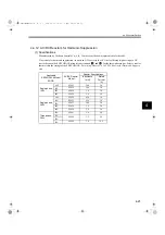
When the regenerative energy exceeds the capacity of the SERVOPACK, install an external regenerative resistor.
The regenerative resistor must be purchased separately by customers. Refer to the table below for selecting the
regenerative resistor. Refer to
5.5 Connecting Regenerative Resistors
for the connection.
(1) References for External Regenerative Resistor
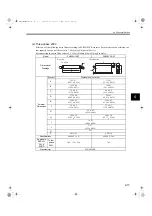
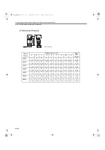
(2) Model Designation
White
AC side
180 to 230 V
DC (Brake) side
No polarity
Red
Black
Yellow
Surge
protector
Surge
protector
Diode
90 to 120 V
DC (Brake) side
No polarity
Diode bridge
AC side
Red
Black
Blue
White
Surge
protector
Surge
protector
Regenerative
Resistor Model
Specifications
Manufacturer
RH120
70 W, 1 to 100
Ω
Iwaki Wireless Research Institute
RH150
90 W, 1 to 100
Ω
RH220
120 W, 1 to 100
Ω
RH300C
200 W, 1 to 10 k
Ω
RH500
300 W, 1 to 30
Ω
RH120 N 10
Ω
J
Model
N: Noninductive winding
Tolerance
Resistance
Code
K
J
H
±
10%
±
5%
±
3%
Tolerance
SIEPS80000025.book 11 ページ 2004年10月25日 月曜日 午前11時57分

