4 Specifications and Dimensional Drawings of Cables and Peripheral Devices
4-2
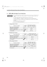
4.1 SERVOPACK Main Circuit Wire Size
1. Wire sizes were selected for three cables per bundle at 40
°
C (104
°
F) ambient temperature with the rated
current.
2. Use cable with a minimum dielectric withstand voltage of 600 V for main circuits.
3. If cables are bundled in PVC or metal ducts, consider the reduction ratio of the allowable current.
4. Use heat-resistant cable under high ambient or panel temperatures where normal vinyl cable will rapidly
deteriorate.
5. Use cable within the allowable moment of inertia.
6. Do not use in continuous regenerating mode.
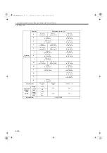
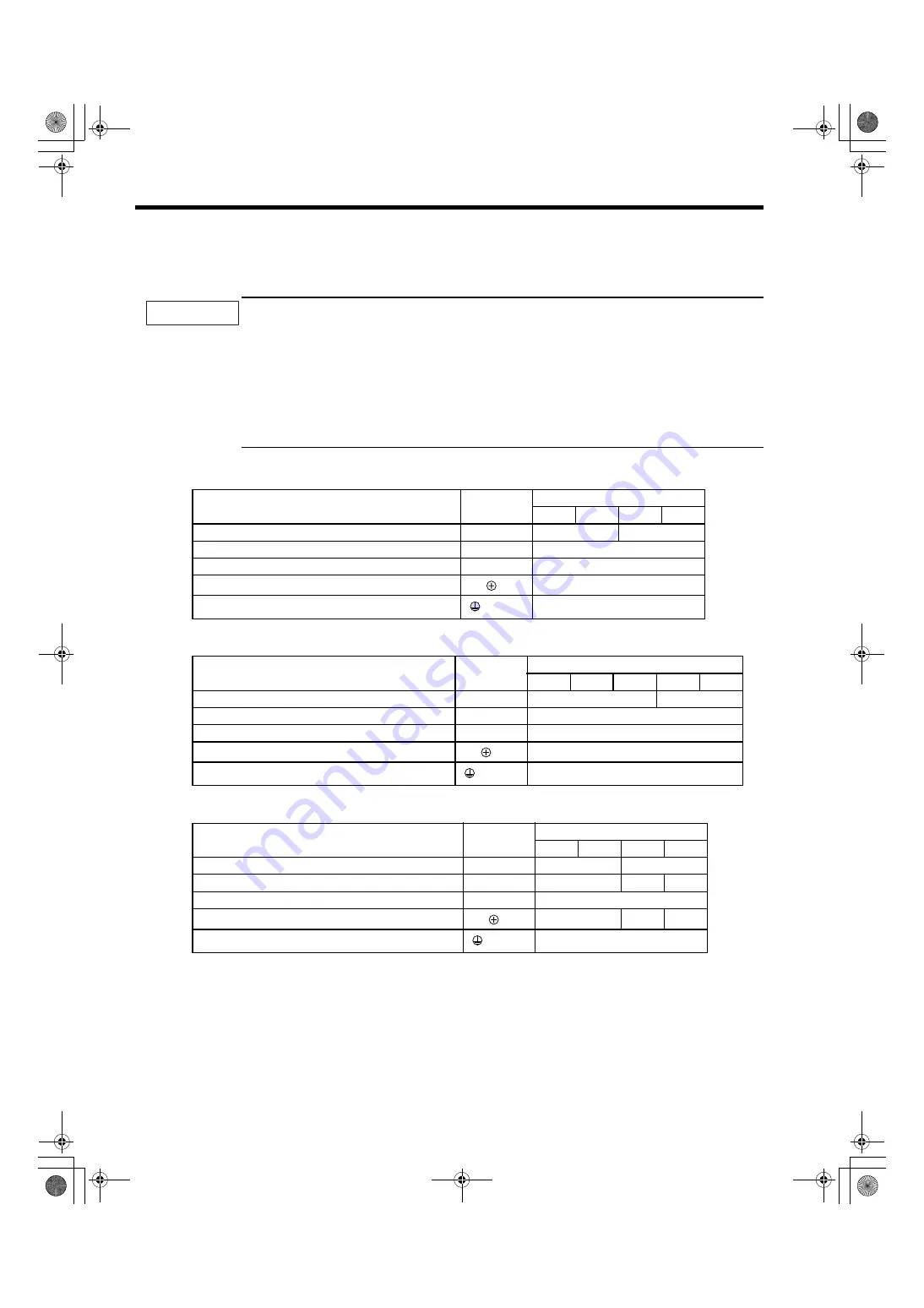
(1) Single-phase for 100 V
(2) Single-phase for 200 V
(3) Three-phase for 200 V
IMPORTANT
External Terminal Name
Terminal
Symbol
SERVOPACK Model SGDS-
A5F
01F
02F
04F
Main circuit power input terminals
L1, L2
HIV1.25
HIV2.0
Servomotor connection terminals
U, V, W
HIV1.25
Control power input terminals
L1C, L2C
HIV1.25
External regenerative resistor connection terminals
B1/
, B2
HIV1.25
Ground terminal
HIV2.0 min.
External Terminal Name
Terminal
Symbol
SERVOPACK Model SGDS-
A5A
01A
02A
04A
08A
Main circuit power input terminals
L1, L2
HIV1.25
HIV2.0
Servomotor connection terminals
U, V, W
HIV1.25
Control power input terminals
L1C, L2C
HIV1.25
External regenerative resistor connection terminal
B1/
, B2
HIV1.25
Ground terminal
HIV2.0 min.
External Terminal Name
Terminal
Symbol
SERVOPACK Model SGDS-
10A
15A
20A
30A
Main circuit power input terminals
L1, L2, L3
HIV2.0
HIV3.5
Servomotor connection terminals
U, V, W
HIV2.0
HIV3.5 HIV5.5
Control power input terminals
L1C, L2C
HIV1.25
External regenerative resistor connection terminals
B1/
, B2
HIV1.25
HIV2.0 HIV3.5
Ground terminal
HIV2.0 min.
SIEPS80000025.book 2 ページ 2004年10月25日 月曜日 午前11時57分


