5 Mechanical & Electrical Installation
20
YASKAWA
TOEPC71061687B Powerlink Option Installation Manual
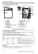
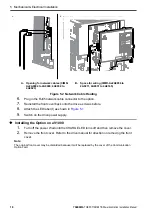
A - Through-hole for ground wire
B - Ground wire
C - Pass ground wire through the bottom
cover of the drive
D - Drive ground terminal
Figure 5.5 Connect Ground Wire
7.
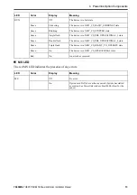
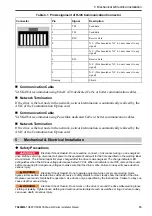
Connect the communication wire to the Communication Option card modular connector.
8.
Attach the cover to the front of the Communication Option card.
9.
Switch on the drive power supply.
◆
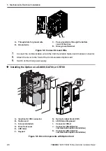
Installing the Option on a GA800, GA700, or CR700
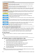
A - Insertion for CN5 connector
B - Option card
C - Screws (included)
D - Drive front cover
E -
LED label
F -
Keypad
G - Option terminal block (CN1)
H - LED Status Ring board
I -
Connector CN5-A
J -
Connector CN5-B (Not for
communication option installation)
K - Connector CN5-C (Not for
communication option installation)
Figure 5.6 Drive Components with Option Card
A B
C
D
C
K
G
J
I
B
A
D
E
F
H

