5 Mechanical & Electrical Installation
26
YASKAWA
TOEPC71061687B Powerlink Option Installation Manual
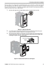
4.
Carefully remove the USB port board (H) and place it on the right side of the drive using
the temporary placement holes. Do not remove the USB port board cable connector.
Figure 5.15 Remove the USB Port Board
5.
Insert the option card (B) into the CN5-A connector (I) on the drive and fasten it into
place using the included screws (C). Tighten both screws to 0.5 to 0.6 Nm (4.4 to 5.3 in.
lbs).
Note:
Installing the option card on a Q2A drive requires only two screws and does not require a ground wire. The
option package ships with three screws and a ground wire for installation on other drive series. Do not use the
ground wire or the extra screw.
Figure 5.16 Insert the Option Card
6.
Firmly connect the communication cable to option terminal block. Install
communications cables apart from main-circuit wiring and other electrical and power
lines. Ensure the cable end is firmly connected.
7.
Reattach and secure the USB port board (H). Use the open space provided inside the
USB port board to route option wiring. Do not pinch cables between the front cover or
the USB port board and the drive.
8.
Install the keypad to the drive after replacing the keypad connector and then the keypad
connector. At that time, insert the keypad connector tab into the drive.
H
Temporary placement holes

