YASKAWA
SIEP C730600 0E YAI Modbus TCP/IP Technical Manual
13
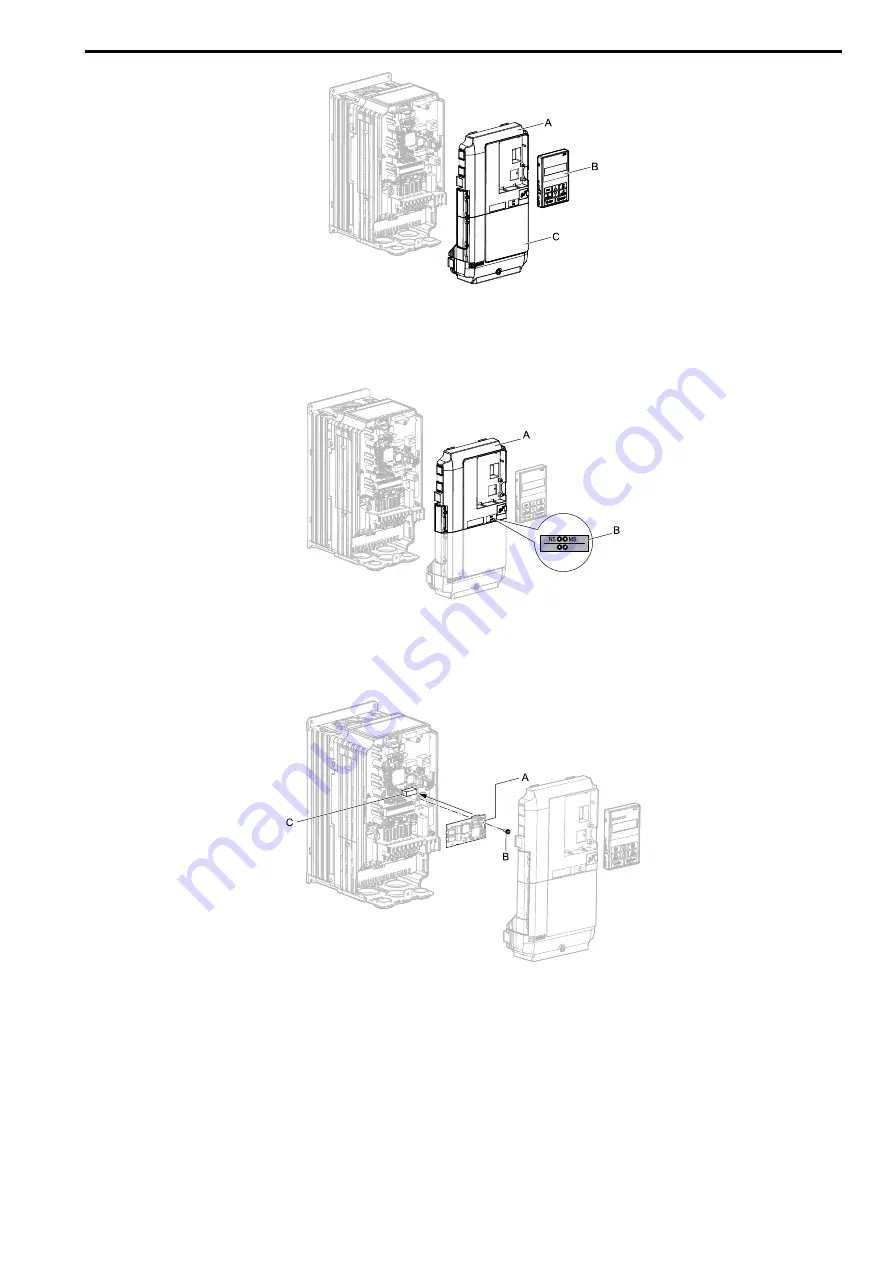
A - Drive front cover
B - Keypad
C - Drive terminal cover
Figure 5.2 Remove the Keypad, Front Cover, and Terminal Cover
2.
Put the LED label (B) in the correct position on the drive front cover (A).
A - Drive front cover
B - LED label
Figure 5.3 Put the LED Label on the Drive Front Cover
3.
Install the option (A) into the CN5-A connector (C) on the drive and use one of the included screws (B) to
put it in place.
A - Option
B - Included screw
C - Connector CN5-A
Figure 5.4 Install the Option
4.
Use one of the remaining included screws (B) to connect one end of the ground wire (C) to the ground
terminal (D). Use the last remaining included screw (B) to connect the other end of the ground wire (C) to
the remaining ground terminal and installation hole on the option (A).
Tighten the screws to a correct tightening torque:
• 0.5 N
∙
m to 0.6 N
∙
m (4.4 in
∙
lb to 5.3 in
∙
lb)


