YASKAWA
SIEP C730600 0E YAI Modbus TCP/IP Technical Manual
17
3.
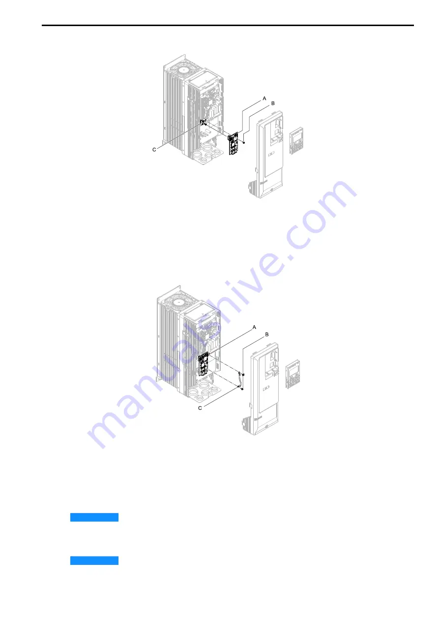
Install the option (A) into the CN5 connector (C) on the drive and use one of the included screws (B) to put
it in place.
A - Option
B - Included screw
C - Connector CN5
Figure 5.11 Install the Option
4.
Use one of the remaining included screws (B) to connect one end of the ground wire (C) to the ground
terminal (A). Use the last remaining included screw (B) to connect the other end of the ground wire (C) to
the remaining ground terminal and installation hole on the option (A).
Tighten the screws to a correct tightening torque:
• 0.5 N
∙
m to 0.6 N
∙
m (4.4 in
∙
lb to 5.3 in
∙
lb)
A - Drive grounding terminal (FE)
B - Included screws
C - Ground wire
Figure 5.12 Connect the Ground Wire
5.
Firmly connect the Ethernet communication cable to the option modular connector CN1 port 1 or port 2.
Isolate communication cables from main circuit wiring and other electrical and power lines. Make sure that
you firmly connect the cable end. (Refer to
). Refer to
Communication Cable Specifications on
for more information.
NOTICE
Damage to Equipment. When you touch the option, make sure that you observe correct electrostatic
discharge (ESD) procedures. If you do not follow procedures, it can cause ESD damage to the drive circuitry.
6.
Reattach the drive front cover (A) and the keypad (B).
Refer to the drive manuals for more information.
NOTICE
Do not pinch cables between the front covers and the drive. Failure to comply could cause
erroneous operation.


