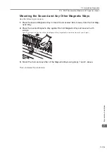
7.2 Installation Procedure
7.2.1 SGLG Servomotors (Coreless Models)
7-3
7
S
ervomotor In
s
tallation
7.2
Installation Procedure
7.2.1
SGLG Servomotors (Coreless Models)
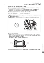
Mounting the Magnetic Way
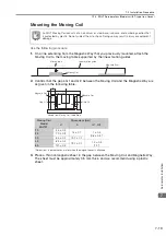
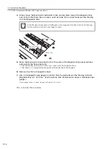
Use the following procedure.
1.
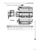
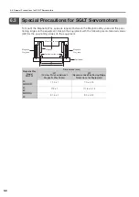
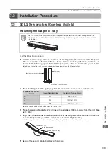
Confirm the mounting reference surfaces of the Magnetic Way and place the Magnetic
Way on one of the reference surfaces. There are two mounting references surfaces, as
shown in the following figure. Select the appropriate reference surface for your system.
Note: Be careful not to pinch your hands between the equipment and the Magnetic Way.
2.
Press the Magnetic Way tightly against the equipment and secure it with screws.
Note:Use socket head screws with a strength class of 10.9.
3.
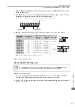
Place the second Magnetic Way in line with and at least 30 mm away from the first Mag-
netic Way.
4.
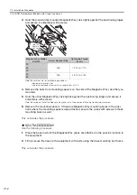
Align the corners of the connecting surfaces of the Magnetic Ways and then rotate the
second Magnetic Way so that it connects to the first Magnetic Way.
Note: The magnetic attraction will pull the Magnetic Ways together. Be careful not to pinch your fingers.
5.
Secure the second Magnetic Way with screws.
The SGLG Magnetic Ways consist of C-shaped steel plates with magnets facing each other
attached between them. Be careful not to let foreign matter (magnetic material) enter between
the magnets.
Magnetic Way Model
SGLGM-
Screw Nominal Size
Tightening Torque (N
cm)
30
M4
360 to 500
40
M5
720 to 1,010
60
90
M6
1,220 to 1,710
Note
Magnet
Nameplate
Mounting reference surface
Mounting reference surface
First Magnetic Way
Second Magnetic Way
Align the corners.
Rotate the Magnetic Way.

