background image

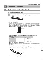
7.2  Installation Procedure

7.2.2  SGLF Servomotors (Models with F-type Iron Cores)

7-8

*

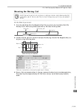
Dimensions in parentheses are for when the magnet cover is attached.

3.

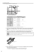
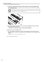
Place a thin nonmagnetic sheet in the gap between the Moving Coil and Magnetic Way. 
The sheet must be approximately 0.5 mm thick, and we recommend using a plastic 
sheet.

4.

Slowly move the Moving Coil toward the Magnetic Way and confirm that there are no 
noises, such as noise from contact between the Moving Coil and Magnetic Way.

5.

Move the Moving Coil back and forth to the ends of the Magnetic Ways several times 
and confirm the following items.

That the Moving Coil does not come into contact with the Magnetic Ways

That there is no foreign matter (magnetic material) between the magnets

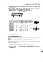
Moving Coil Model

Dimensions (mm)

H

P

G (Gap)

SGLFW-

20

45 

±

 0.1

22 

±

 0.2

1

(0.8)

*

35

21 

±

 0.2

50

58 

±

 0.1

25.8 

±

 0.2

1Z

27 

±

 0.2

SGLFW2-

30A070

40 

±

 0.1

27.5 

±

 0.2

0.8

30A120

20 

±

 0.2

30A230

45

50 

±

 0.1

26 

±

 0.2

90

30 

±

 0.2

1D

42.5 

±

 0.2

As the Moving Coil approaches the Magnetic Way, magnetic attraction will pull on the Moving 
Coil. Be careful not to pinch your fingers or tools.

Gap, G

H

P

Moving Coil

Magnetic Way

Mounting hole

Side of Linear Servomotor 

(viewed from side of Moving Coil cable)

Cable

Reference mark

Important

Nonmagnetic sheet

Move the Moving 
Coil slowly.

Moving Coil

Summary of Contents for SIGMA-7 Series

Page 1: ...Design Precautions Servomotor Installation Connecting Linear Encoders Maintenance and Inspection Specifications Ratings and External Dimensions of SGLG Servomotors Connections between Servomotors and...

Page 2: ...liability is assumed with respect to the use of the informa tion contained herein Moreover because Yaskawa is constantly striving to improve its high quality products the information contained in this...

Page 3: ...Servomotors and gives their specifications ratings and external dimensions 4 Specifications Ratings and External Dimensions of SGLF Servomotors Describes how to interpret the model numbers of SGLF Se...

Page 4: ...Ks 7S and 7W SERVOPACKs with Built in Controllers 7C Servomotors Other Documents Built in Function Manuals 7 Series 7S 7W SERVOPACK Product Manuals 7 Series 7S 7W SERVOPACK Hardware Option Product Man...

Page 5: ...iled information on the specifications system configu ration and communications con nection methods for the Ethernet communications that are used with MP3000 Series Machine Control lers and 7 Series 7...

Page 6: ...d procedures for installing the Safety Module in a SERVOPACK V Series V Series for Large Capacity Models 7 Series Installation Guide INDEXER Module TOBP C720829 02 Provides detailed procedures for ins...

Page 7: ...Command Option Attachable Type with INDEXER Module Product Manual SIEP S800001 64 7 Series AC Servo Drive 7S SERVOPACK Command Option Attachable Type with DeviceNet Module Product Manual SIEP S800001...

Page 8: ...ation for Transfer and Alignment Application Product Manual SIEP S800001 95 7 Series AC Servo Drive 7S SERVOPACK with FT EX Specification for Torque Force Assistance for Conveyance Application Product...

Page 9: ...C Servo Drive Direct Drive Servomotor Product Manual SIEP S800001 38 7 Series Peripheral Device Selection Manual 7 Series AC Servo Drive Peripheral Device Selection Manual SIEP S800001 32 Provides the...

Page 10: ...ing Tool MPE720 Version 7 User s Manual SIEP C880761 03 Describes in detail how to operate MPE720 version 7 7 Series AC Servo Drive Digital Operator Operating Manual SIEP S800001 33 Describes the oper...

Page 11: ...tor A 7 Series Linear Servomotor SERVOPACK A 7 Series Servo Amplifier Servo Drive The combination of a Servomotor and SERVOPACK Main Circuit Cable One of the cables that connect to the main circuit te...

Page 12: ...ation marked as shown below is important for safety Always read this information and heed the precau tions that are provided DANGER Indicates precautions that if not heeded are likely to result in los...

Page 13: ...ternal Dynamic Brake Resistors Servo motors and other components can be very hot while power is ON or soon after the power is turned OFF Implement safety measures such as installing covers so that han...

Page 14: ...ooseness before you use them to move the Linear Servomotor There is a risk of injury or damage Do not use the eyebolts on a SERVOPACK or Servomotor to move the machine There is a risk of damage or inj...

Page 15: ...nsure safety and prevent accidents observe the following precautions when you install the Linear Servomo tor Do not bring magnetic substances including Moving Coils and tools near the Magnetic Way The...

Page 16: ...agnetic cards on your person or bring such devices or media near a Magnetic Way The influence of the magnetism may cause the device or media to malfunction or fail Use the product in an environment th...

Page 17: ...y after all wiring including the main circuit termi nals has been completed If a connector is used for the main circuit terminals remove the main circuit connector from the SER VOPACK before you wire...

Page 18: ...turn OFF the main cir cuit power supply or control power supply during operation before you turn OFF the servo the Servomotor will stop as follows If you turn OFF the main circuit power supply during...

Page 19: ...age may still remain in the SERVOPACK even after turning OFF the power supply There is a risk of electric shock WARNING The product may suddenly start to operate when the power supply is recovered aft...

Page 20: ...products shown in illustrations in this document are sometimes shown without covers or protective guards Always replace all covers and protective guards before you use the product If you need a new c...

Page 21: ...red product in a manner in which it was not originally intended Causes that were not foreseeable with the scientific and technological understanding at the time of shipment from Yaskawa Events for whi...

Page 22: ...property Systems that require a high degree of reliability such as systems that supply gas water or electricity or systems that operate continuously 24 hours a day Other systems that require a similar...

Page 23: ...in compliance with the UL Standards Estimates are available for those prod ucts Contact your Yaskawa representative for details Product Model UL Standards UL File No SERVOPACKs SGD7S SGD7W UL 61800 5...

Page 24: ...00 5 1 RoHS Directive 2011 65 EU EN 50581 Rotary Servomotors SGMMV EMC Directive 2004 108 EC EN 55011 group 1 class A EN 61000 6 2 EN 61800 3 Category C2 Second environment Low Voltage Directive 2006...

Page 25: ...EC 62061 SILCL3 Mission Time IEC 61508 10 years 20 years Probability of Dangerous Failure per Hour IEC 61508 IEC 62061 PFH 4 04 10 9 1 h 4 04 of SIL3 PFH 4 05 10 9 1 h 4 05 of SIL3 Performance Level E...

Page 26: ...tors and SERVOPACKs 1 5 Capacity Selection 2 2 1 Selecting the Servomotor Capacity 2 2 Specifications Ratings and External Dimensions of SGLG Servomotors 3 3 1 Model Designations 3 2 3 1 1 Moving Coil...

Page 27: ...vomotor Overload Protection Characteristics 4 12 4 3 Ratings and Specifications SGLFW Models 4 13 4 3 1 Specifications 4 13 4 3 2 Ratings 4 14 4 3 3 Force Motor Speed Characteristics 4 15 4 3 4 Servom...

Page 28: ...Main Circuit Cables 5 27 Equipment Design Precautions 6 6 1 Influence of Magnetic Attraction 6 2 6 1 1 SGLF Servomotors 6 2 6 1 2 SGLT Servomotors 6 3 6 2 Influence of Magnetic Way Leakage Flux 6 4 6...

Page 29: ...coders from Mitutoyo Corporation 8 5 8 2 6 Linear Encoders from Magnescale Co Ltd 8 5 8 3 Adjusting Linear Encoders 8 6 Connections between Servomotors and SERVOPACKs 9 9 1 Selecting Cables 9 2 9 1 1...

Page 30: ...art Names 1 2 1 1 1 SGLG Servomotors 1 2 1 1 2 SGLF Servomotors 1 2 1 1 3 SGLT Servomotors 1 2 1 2 Interpreting the Nameplates 1 3 1 2 1 Moving Coils 1 3 1 2 2 Magnetic Ways 1 3 1 3 Outline of Model D...

Page 31: ...motor Main Circuit Cable Note The Moving Coil nameplate is attached here Enclosed cable Sensor Cable Dummy plate to reduce magnetic force Magnet Cover Magnetic Way yoke Cardboard Condition with Cardbo...
Page 32: ...Ins B B LINEAR SERVO MOTOR 1120 78 Hz 3 Ph 4 4 5 2 2 R0B205 101 001 1W 840 SUD Order number Rated force rated motor speed number of phases and rated current frequency Rated output power supply voltag...

Page 33: ...it on G F T Chapter 3 Chapter 4 Chapter 5 Coreless models Models with F type iron core Models with T type iron core Code Specification W W2 M M2 Moving Coil Magnetic Way The specifications for the 3rd...
Page 34: ...Models Used with High Force Magnetic Way SGLGW 40A140C 57 230 1R6A or 2R1F 1R6A SGLGW 40A253C 114 460 2R8A or 2R8F 2R8A SGLGW 40A365C 171 690 3R8A 5R5A SGLGW 60A140C 85 360 1R6A or 2R1F 1R6A SGLGW 60A...

Page 35: ...SGLTW 35A170H 300 600 SGLTW 35A320A 440 1320 120A SGLTW 35A320H 600 1200 SGLTW 35A460A 670 2000 180A SGLTW 40A400B 670 2600 SGLTW 40A600B 1000 4000 330A SGLTW 50A170H 450 900 5R5A SGLTW 50A320H 900 1...

Page 36: ...This chapter describes calculation methods to use when selecting Servomotor capacities 2 1 Selecting the Servomotor Capacity 2 2 Capacity Selection 2...

Page 37: ...Linear Servomotor Selection Conditions FP Maximum force 0 9 Fs Maximum force 0 9 Frms Rated force 0 9 The following Servomotor Moving Coil and Magnetic Way meet the selection conditions SGLGW 60A253C...

Page 38: ...ification of Effective Force 7 Result It has been verified that the provisionally selected Servomotor is applicable Item Value Maximum Force 440 N Rated Force 140 N Moving Coil Mass mM 0 82 kg Servomo...

Page 39: ...Ratings With Standard Force Magnetic Way 3 6 3 2 3 Force Motor Speed Characteristics 3 7 3 2 4 Servomotor Overload Protection Characteristics 3 8 3 2 5 Specifications With High Force Magnetic Way 3 9...

Page 40: ...n G K All models Connector from Interconnectron GmbH None None Self cooled All models All models Air cooled Air cooled Self cooled None Yes Yes Polarity Sensor Hall Sensor Cooling Method Length of Mov...

Page 41: ...5 252 360 405 432 450 504 S G L G M 30 108 A Same as for the Moving Coil Magnetic Way Same as for the Moving Coil Length of Magnetic Way Options Standard force All models High force 9th digit M 90 mm...

Page 42: ...tion Incorrect Installation Total Length of Moving Coil with Polarity Sensor Hall Sensor Note Polarity sensor hall sensor Edge of Magnetic Way Magnetic Way Moving Coil Moving Coil movement direction P...

Page 43: ...or air cooled Only self cooled models are available for the SGLGW 30A Protective Structure IP00 Environ mental Condi tions Surrounding Air Tempera ture 0 C to 40 C with no freezing Surrounding Air Hu...

Page 44: ...s 5 0 5 0 5 0 5 0 5 0 4 8 4 8 4 8 4 0 4 0 4 0 Rated Force 1 2 N 12 5 25 47 93 140 70 140 210 325 550 750 Maximum Force 1 N 40 80 140 280 420 220 440 660 1300 2200 3000 Rated Current 1 Arms 0 51 0 79...

Page 45: ...40A365C A B SGLGW 40A140C A B SGLGW 40A253C A B SGLGW 30A050C 6 5 4 3 2 1 0 6 5 4 3 2 1 0 6 5 4 3 2 1 0 6 5 4 3 2 1 0 6 5 4 3 2 1 0 6 5 4 3 2 1 0 6 5 4 3 2 1 0 6 5 4 3 2 1 0 6 5 4 3 2 1 0 6 5 4 3 2 1...

Page 46: ...he Servomotor so that the effective force remains within the continu ous duty zone given in 3 2 3 Force Motor Speed Characteristics on page 3 7 SGLGW 30A 10000 1000 100 10 1 350 50 100 150 200 250 300...

Page 47: ...times Vibration Resistance Vibration Acceleration Rate 49 m s2 the vibration resistance in three directions vertical side to side and front to back Linear Servomotor Moving Coil Model SGLGW 40A 60A 14...

Page 48: ...intermittent duty zone depend on the power supply voltage 3 If the effective force is within the allowable range for the rated force the Servomotor can be used within the intermittent duty zone 4 If...

Page 49: ...on characteristics do not mean that you can perform continuous duty operation with an output of 100 or higher Use the Servomotor so that the effective force remains within the continu ous duty zone gi...

Page 50: ...nal drawings of the Moving Coil Plug 350779 1 Pins 350924 1 or 770672 1 From Tyco Electronics Japan G K Mating Connector Cap 350780 1 Socket 350925 1 or 770673 1 Polarity Sensor Hall Sensor Connector...

Page 51: ...imensional drawings of the Moving Coil Extension SROC06JMSCN169 Pins 021 423 1020 From Interconnectron GmbH Mating Connector Plug SPUC06KFSDN236 Socket 020 030 1020 Polarity Sensor Hall Sensor Connect...

Page 52: ...e Magnetic Ways SGLGM 30 A Magnetic Way Model SGLGM L1 L2 N Approx Mass kg 30108A 108 54 2 0 6 30216A 216 162 4 1 1 30432A 432 378 8 2 3 Pitch 54 L1 1 unit Pitch 54 Unit mm 8 dia 5 N 4 5 dia 27 27 44...

Page 53: ...arrow in the dimensional drawings of the Moving Coil Plug 350779 1 Pins 350561 3 or 350690 3 No 1 to 3 350654 1 or 350669 1 No 4 From Tyco Electronics Japan G K Mating Connector Cap 350780 1 Socket 3...

Page 54: ...ings of the Moving Coil Extension SROC06JMSCN169 Pins 021 423 1020 From Interconnectron GmbH Mating Connector Plug SPUC06KFSDN236 Socket 020 030 1020 Polarity Sensor Hall Sensor Connector Pin connecto...

Page 55: ...GLGM L1 L2 N Approx Mass kg Standard Force 40090C or 40090CT 90 45 2 0 8 40225C or 40225CT 225 180 5 2 0 40360C or 40360CT 360 315 8 3 1 40405C or 40405CT 405 360 9 3 5 40450C or 40450CT 450 405 10 3...

Page 56: ...r 40090CT M 90 45 2 1 0 40225C M or 40225CT M 225 180 5 2 6 40360C M or 40360CT M 360 315 8 4 1 40405C M or 40405CT M 405 360 9 4 6 40450C M or 40450CT M 450 405 10 5 1 Pitch 45 L1 1 unit SGLGM CT M o...

Page 57: ...e arrow in the dimensional drawings of the Moving Coil Plug 350779 1 Pins 350561 3 or 350690 3 No 1 to 3 350654 1 or 350669 1 No 4 From Tyco Electronics Japan G K Mating Connector Cap 350780 1 Socket...

Page 58: ...ings of the Moving Coil Extension SROC06JMSCN169 Pins 021 423 1020 From Interconnectron GmbH Mating Connector Plug SPUC06KFSDN236 Socket 020 030 1020 Polarity Sensor Hall Sensor Connector Pin connecto...

Page 59: ...GLGM L1 L2 N Approx Mass kg Standard Force 60090C or 60090CT 90 45 2 1 1 60225C or 60225CT 225 180 5 2 6 60360C or 60360CT 360 315 8 4 1 60405C or 60405CT 405 360 9 4 6 60450C or 60450CT 450 405 10 5...

Page 60: ...r 60090CT M 90 45 2 1 3 60225C M or 60225CT M 225 180 5 3 3 60360C M or 60360CT M 360 315 8 5 2 60405C M or 60405CT M 405 360 9 5 9 60450C M or 60450CT M 450 405 10 6 6 10 dia 5 4 SGLGM CT M only Unit...

Page 61: ...ow in the dimensional drawings of the Moving Coil Plug 350779 1 Pins 350218 3 or 350547 3 No 1 to 3 350654 1 or 350669 1 No 4 From Tyco Electronics Japan G K Mating Connector Cap 350780 1 Socket 35053...

Page 62: ...ic Ways SGLGM 90 A Magnetic Way Model SGLGM L1 L2 N Approx Mass kg 90252A 252 189 4 7 3 90504A 504 441 8 14 7 L1 1 unit Pitch 63 N 6 6 dia Pitch 63 12 dia 6 6 dia Unit mm 12 dia 6 5 X X 6 5 50 8 110 1...

Page 63: ...ual for the following information Cable dimensional drawings and cable connection specifications Order numbers and specifications of individual connectors for cables Order numbers and specifications f...

Page 64: ...E 5 m JZSP CLN11 05 E 10 m JZSP CLN11 10 E 15 m JZSP CLN11 15 E 20 m JZSP CLN11 20 E SGLGW 90A 1 m JZSP CLN21 01 E 3 m JZSP CLN21 03 E 5 m JZSP CLN21 05 E 10 m JZSP CLN21 10 E 15 m JZSP CLN21 15 E 20...

Page 65: ...pecifications 4 6 4 2 2 Ratings Self Cooled Models 4 7 4 2 3 Force Motor Speed Characteristics Self Cooled Models 4 9 4 2 4 Ratings Water Cooled Models 4 10 4 2 5 Force Motor Speed Characteristics Wat...

Page 66: ...5 4 4 4 SGLFW2 90 Water Cooled Models 4 28 4 4 5 SGLFW2 90 Self Cooled and Water Cooled Models 4 30 4 4 6 SGLFW2 1D 4 31 4 4 7 SGLFW 20 4 34 4 4 8 SGLFW 35 4 36 4 4 9 SGLFW 50 4 39 4 4 10 SGLFW 1Z 4 4...

Page 67: ...ooled 200 VAC Servomotor Type Power Supply Voltage Length of Moving Coil Design Revision Order Magnet Height Moving Coil Magnetic Way 1st digit 3rd 4th digits 2nd digit 11th digit 9th digit 6th 7th 8t...

Page 68: ...th digits 2nd digit 11th digit 9th digit 6th 7th 8th digits 5th digit 10th digit 3rd 4th digits 1st digit Linear Series Linear Servomotors 2nd digit 5th digit 6th 7th 8th digits 9th digit 10th digit 1...

Page 69: ...correct Installation Total Length of Moving Coil with Polarity Sensor Hall Sensor Note Polarity sensor hall sensor Moving Coil movement direction Magnetic Way Moving Coil Edge of Magnetic Way Polarity...

Page 70: ...Structure IP00 Environ mental Condi tions Surrounding Air Temperature 0 C to 40 C with no freezing Surrounding Air Humidity 20 to 80 relative humidity with no condensation Installation Site Must be i...

Page 71: ...20 Linear Servomotor Moving Coil Model SGLFW2 30A 45A 070A 1 120A 1 230A 1 200A 1 380A 1 Rated Motor Speed Reference Speed during Speed Control 1 m s 4 0 4 0 4 0 4 0 4 0 Maximum Speed 1 m s 5 0 5 0 5...

Page 72: ...vomotor Moving Coil Model SGLFW2 90A 1DA 200A 1 380A 1 560A 1 380A 1 560A 1 Rated Motor Speed Reference Speed during Speed Control 1 m s 4 0 4 0 4 0 2 0 2 0 Maximum Speed 1 m s 4 0 4 0 4 0 2 5 2 5 Rat...

Page 73: ...SGD7S 180A SGLFW2 30A230A 1 Combined with SGD7 2R8A SGLFW2 30A230A 1 Combined with SGD7S 3R8A SGLFW2 30A120A 1 6 5 4 3 2 1 0 0 50 100 150 A B 6 5 4 3 2 1 0 0 100 200 300 A B A B 6 5 4 3 2 1 0 A B 6 5...

Page 74: ...Control 1 m s 4 0 Maximum Speed 1 m s 4 0 Rated Force 1 2 N 896 Maximum Force 1 N 1680 Rated Current 1 Arms 11 5 Maximum Current 1 Arms 26 9 Moving Coil Mass kg 6 1 Force Constant N Arms 82 0 BEMF Con...

Page 75: ...stics in the intermittent duty zone depend on the power supply voltage 3 If the effective force is within the allowable range for the rated force the Servomotor can be used within the intermittent dut...

Page 76: ...effective force remains within the continu ous duty zone given in 4 2 3 Force Motor Speed Characteristics Self Cooled Models on page 4 9 and on page 4 11 400 350 50 100 150 200 250 300 SGLFW2 30A070A...

Page 77: ...Self cooled Protective Structure IP00 Environmen tal Conditions Surrounding Air Temperature 0 C to 40 C with no freezing Surrounding Air Humidity 20 to 80 relative humidity with no condensation Insta...

Page 78: ...ce Speed during Speed Control 1 m s 5 0 3 5 2 5 3 0 1 5 1 5 1 5 1 5 Maximum Speed 1 m s 5 0 5 0 5 0 5 0 5 0 5 0 4 9 4 9 Rated Force 1 2 N 25 40 80 160 280 560 560 1120 Maximum Force 1 N 86 125 220 440...

Page 79: ...que motor speed characteristics will become smaller because the voltage drop increases SGLFW 20A090A 6 5 4 3 2 1 0 6 5 4 3 2 1 0 6 5 4 3 2 1 0 6 5 4 3 2 1 0 6 5 4 3 2 1 0 6 5 4 3 2 1 0 6 5 4 3 2 1 0 6...

Page 80: ...ntinuous duty operation with an output of 100 or higher Use the Servomotor so that the effective force remains within the continu ous duty zone given in 4 3 3 Force Motor Speed Characteristics on page...

Page 81: ...90 02 D8C CG From DDK Ltd Mating Connector Socket connector 17JE 13090 02 D8C A CG Studs 17L 002C or 17L 002C1 SGLFW2 30A070AS 50 min 31 15 14 29 40 18 20 3 M4 8 Polarity sensor hall sensor Magnetic W...

Page 82: ...r 17JE 13090 02 D8C A CG Studs 17L 002C or 17L 002C1 Gap 0 8 Thermal protector relay connector Molex Japan LLC Polarity sensor hall sensor Polarity sensor hall sensor and thermal protector cable UL202...

Page 83: ...le housing 5557 02R Terminals 5556T or 5556TL From Molex Japan LLC Mating Connector Plug housing 5559 02P Terminals 5558T or 5558TL Magnetic Way 50 min Servomotor Main Circuit Cable UL2586 AWG19 Refer...

Page 84: ...r 5556TL From Molex Japan LLC Mating Connector Plug housing 5559 02P Terminals 5558T or 5558TL 50 min Magnetic Way Servomotor Main Circuit Cable UL2586 AWG19 Thermal protector cable UL1333 AWG20 Therm...

Page 85: ...hem are aligned in the same direction as shown in the figure Magnetic Way Model SGLFM2 L1 0 1 L2 N Approx Mass kg 30270A 270 225 45 5 6 0 9 30450A 450 405 45 9 10 1 5 30630A 630 585 45 13 14 2 0 N S N...

Page 86: ...r 17JE 13090 02 D8C A CG Studs 17L 002C or 17L 002C1 Thermal protector relay connector Molex Japan LLC 50 min Polarity sensor hall sensor Polarity sensor hall sensor and thermal protector cable UL2027...

Page 87: ...5557 02R Terminals 5556T or 5556TL From Molex Japan LLC Mating Connector Plug housing 5559 02P Terminals 5558T or 5558TL Gap 0 8 11 36 2 22 5 23 6 37 5 37 5 46 9 69 5 48 5 55 L1 L2 L3 50 0 1 75 14 5...

Page 88: ...tion as shown in the figure Magnetic Way Model SGLFM2 L1 0 1 L2 N Approx Mass kg 45306A 306 204 102 2 3 1 5 45510A 510 408 102 4 5 2 5 45714A 714 612 102 6 7 3 4 N S N S N S 6 102 37 5 63 6 6 75 L2 51...

Page 89: ...or cable UL20276 AWG28 Refertothefollowingtable 50 min Polarity sensor hall sensor Magnetic Way 2 4 40 UNC screws 60 min Refer to the following figures and The Moving Coil moves in the direction indic...

Page 90: ...r Socket connector 17JE 13090 02 D8C A CG Studs 17L 002C or 17L 002C1 Vu Vv Vw Su Sv Sw 0 180 360 540 Electrical angle Inverse power V A1 B1 B2 A2 A1 Phase U Red A2 Phase V White B1 Phase W Black B2 F...

Page 91: ...544 300 30 0 3 14 9 90A560AT1H 500 50 Connector Specifications Servomotor Connector Tab housing 1 917808 2 Contacts 917803 2 A1 A2 and B1 84695 1 B2 From Tyco Electronics Japan G K Mating Connector Re...

Page 92: ...nsor Hall Sensor and Thermal Protector Connector Pin connector 17JE 23090 02 D8C CG From DDK Ltd Mating Connector Socket connector 17JE 13090 02 D8C A CG Studs 17L 002C or 17L 002C1 60 60 1 5 120 11 2...

Page 93: ...1 917807 2 Contacts 179956 2 Thermal Protector Connector Receptacle housing 5557 02R Terminals 5556T or 5556TL From Molex Japan LLC Mating Connector Plug housing 5559 02P Terminals 5558T or 5558TL 60...

Page 94: ...marks on them are aligned in the same direction as shown in the figure Magnetic Way Model SGLFM2 L1 0 1 L2 N Approx Mass kg 90306A 306 204 102 2 3 2 6 90510A 510 408 102 4 5 4 2 90714A 714 612 102 6...

Page 95: ...r Socket connector 17JE 13090 02 D8C A CG Studs 17L 002C or 17L 002C1 UL20276 AWG28 Thermal protector relay connector Molex Japan LLC Receptacle housing 5557 02R Plug housing 5559 02P 50 min Polarity...

Page 96: ...090 02 D8C A CG Studs 17L 002C or 17L 002C1 Magnetic Way Servomotor Main Circuit Cable UL2586 AWG12 Servomotor connector 60 min Thermal protector cable UL1333 AWG20 Thermal protector connector 1 0 5 d...

Page 97: ...hem are aligned in the same direction as shown in the figure Magnetic Way Model SGLFM2 L1 0 1 L2 N Approx Mass kg 1D306A 306 204 102 2 3 3 7 1D510A 510 408 102 4 5 6 2 1D714A 714 612 102 6 7 8 6 L2 17...

Page 98: ...36 3 or 350550 3 Polarity Sensor Hall Sensor Connector Pin connector 17JE 23090 02 D8C CG From DDK Ltd Mating Connector Socket connector 17JE 13090 02 D8C A CG Studs 17L 002C or 17L 002C1 Unit mm 2 M4...

Page 99: ...in the figure Magnetic Way Model SGLFM L1 L2 L3 LA N Approx Mass kg 20324A 324 270 54 5 331 6 30 8 6 0 9 20540A 540 486 54 9 547 6 30 8 10 1 4 20756A 756 702 54 13 763 6 30 8 14 2 Gap 1 S N S N 6 9 9...

Page 100: ...6 3 or 350550 3 Polarity Sensor Hall Sensor Connector Pin connector 17JE 23090 02 D8C CG From DDK Ltd Mating Connector Socket connector 17JE 13090 02 D8C A CG Studs 17L 002C or 17L 002C1 SGLFW 35A120A...

Page 101: ...170 Socket 020 105 1020 Polarity Sensor Hall Sensor Connector Pin connector 17JE 23090 02 D8C CG From DDK Ltd Mating Connector Socket connector 17JE 13090 02 D8C A CG Studs 17L 002C or 17L 002C1 SGLFW...

Page 102: ...SGLFM L1 L2 L3 LA N Approx Mass kg 35324A 324 270 54 5 334 4 32 2 6 1 2 35540A 540 486 54 9 550 4 32 2 10 2 35756A 756 702 54 13 766 4 32 2 14 2 9 L1 L2 Gap 1 34 S S N S S N N N L3 6 10 4 45 0 1 60 5...

Page 103: ...nector Cap 350780 1 Socket 350536 3 or 350550 3 Polarity Sensor Hall Sensor Connector Pin connector 17JE 23090 02 D8C CG From DDK Ltd Mating Connector Socket connector 17JE 13090 02 D8C A CG Studs 17L...

Page 104: ...rity Sensor Hall Sensor Connector Pin connector 17JE 23090 02 D8C CG From DDK Ltd Mating Connector Socket connector 17JE 13090 02 D8C A CG Studs 17L 002C or 17L 002C1 SGLFW 50A200B D SGLFW 50A380B D 6...

Page 105: ...re Magnetic Way Model SGLFM L1 L2 L3 LA N Approx Mass kg 50405A 405 337 5 67 5 5 416 3 39 4 6 2 8 50675A 675 607 5 67 5 9 686 3 39 4 10 4 6 50945A 945 877 5 67 5 13 956 3 39 4 14 6 5 Gap 1 2 N 5 8 dia...

Page 106: ...Socket 350536 3 or 350550 3 Polarity Sensor Hall Sensor Connector Pin connector 17JE 23090 02 D8C CG From DDK Ltd Mating Connector Socket connector 17JE 13090 02 D8C A CG Studs 17L 002C or 17L 002C1 9...

Page 107: ...From DDK Ltd Mating Connector Socket connector 17JE 13090 02 D8C A CG Studs 17L 002C or 17L 002C1 43 9 0 5 62 5 62 5 125 3 40 119 61 5 57 5 7 60 96 112 40 30 15 215 120 60 2 55 25 10 180 35 5 35 5 60...

Page 108: ...kg 1Z405A 405 337 5 67 5 5 423 9 43 2 6 5 1Z675A 675 607 5 67 5 9 693 9 43 2 10 8 3 1Z945A 945 877 5 67 5 13 963 9 43 2 14 12 125 112 6 5 6 5 62 5 62 5 61 5 57 5 119 43 2 67 5 14 9 5 58 0 1 43 Gap1 S...

Page 109: ...owing information Cable dimensional drawings and cable connection specifications Order numbers and specifications of individual connectors for cables Order numbers and specifications for wiring materi...

Page 110: ...03 03 E 5 m JZSP CL2N703 05 E 10 m JZSP CL2N703 10 E 15 m JZSP CL2N703 15 E 20 m JZSP CL2N703 20 E SGLFW2 45A200A SGLFW2 45A380A 1 m JZSP CL2N603 01 E 3 m JZSP CL2N603 03 E 5 m JZSP CL2N603 05 E 10 m...

Page 111: ...isted above SGLFW2 90A A L and SGLFW2 1D A L 1 Connector from Tyco Electronics Japan G K 2 Connector from Interconnectron GmbH SGLFW2 90A200A L 1 m JZSP CLN423 01 E 3 m JZSP CLN423 03 E 5 m JZSP CLN42...

Page 112: ...Ratings 5 6 5 2 3 Force Motor Speed Characteristics 5 7 5 2 4 Servomotor Overload Protection Characteristics 5 9 5 3 External Dimensions 5 10 5 3 1 SGLTW 20 Standard Models 5 10 5 3 2 SGLTW 35 Standa...

Page 113: ...cification Code W Moving Coil Specification 3rd 4th digits Magnet Height Code 20 35 40 50 80 20 mm 36 mm 40 mm 51 mm 76 5 mm Specification Code 170 320 400 460 600 170 mm 315 mm 394 2 mm 460 mm 574 2...

Page 114: ...ength of Magnetic Way Servomotor Type 8th digit Design Revision Order S G L T M 20 324 A 3rd 4th digits 5th 6th 7th digits Specification 2nd digit Moving Coil Magnetic Way Magnet Height Code M Magneti...

Page 115: ...ble Correct Installation Incorrect Installation Total Length of Moving Coil with Polarity Sensor Hall Sensor Note Moving Coil Polarity sensor hall sensor Magnetic Way Moving Coil movement direction Ed...

Page 116: ...agnet Cooling Method Self cooled Protective Structure IP00 Environ mental Condi tions Surround ing Air Tempera ture 0 C to 40 C with no freezing Surround ing Air Humidity 20 to 80 relative humidity wi...

Page 117: ...00 600 1200 900 1800 Rated Current 1 Arms 2 3 4 4 6 7 3 5 7 0 10 7 7 3 10 9 11 1 17 1 5 1 10 1 5 1 10 2 Maximum Current 1 Arms 7 7 15 4 23 2 12 1 24 2 36 7 39 4 60 6 57 9 86 9 11 9 23 9 11 8 23 6 Movi...

Page 118: ...smaller because the voltage drop increases Continuous duty zone Intermittent duty zone solid lines With three phase 200 V input dotted lines With single phase 200 V input A B A B 0 400 800 1200 1400...

Page 119: ...in the allowable range for the rated force the Servomotor can be used within the intermittent duty zone 4 If you use a Servomotor Main Circuit Cable that exceeds 20 m the intermittent duty zone in the...

Page 120: ...perform continuous duty operation with an output of 100 or higher Use the Servomotor so that the effective force remains within the continu ous duty zone given in 5 2 3 Force Motor Speed Characteristi...

Page 121: ...No 1 to 3 350654 1 or 350669 1 No 4 From Tyco Electronics Japan G K Mating Connector Cap 350780 1 Socket 350537 3 or 350550 3 Polarity Sensor Hall Sensor Connector Pin connector 17JE 23090 02 D8C CG...

Page 122: ...ting screws Do not use stainless steel screws Magnetic Way Model SGLTM L1 L2 LA LB LC LD N Approx Mass kg 20324A 324 270 54 5 31 7 13 7 40 3 62 6 3 4 20540A 540 486 54 9 31 7 13 7 40 3 62 10 5 7 20756...

Page 123: ...324 270 310 162 162 6 2 5 1 20540AY 540 486 526 378 189 10 3 8 5 20756AY 756 702 742 594 198 14 4 12 Base Moving Coil 2 N2 10 dia Refer to Side to Side Cross Section for the depth Unit mm Includes a...

Page 124: ...s 350218 3 or 350547 3 No 1 to 3 350654 1 or 350669 1 No 4 From Tyco Electronics Japan G K Mating Connector Cap 350780 1 Socket 350537 3 or 350550 3 Polarity Sensor Hall Sensor Connector Pin connector...

Page 125: ...ainless steel screws Magnetic Way Model SGLTM L1 L2 LA LB LC LD N Approx Mass kg 35324A 324 270 54 5 33 15 39 62 6 4 8 35540A 540 486 54 9 33 15 39 62 10 8 35756A 756 702 54 13 33 15 39 62 14 11 Movin...

Page 126: ...2 L3 L4 L5 N1 N2 Approx Mass kg 35324AY 324 270 310 162 162 6 2 6 4 35540AY 540 486 526 378 189 10 3 11 35756AY 756 702 742 594 198 14 4 15 Base Moving Coil 2 N2 10 dia Refer to Side to Side Cross Sec...

Page 127: ...ving Coil Polarity Sensor Hall Sensor Connector Pin connector 17JE 23090 02 D8C CG From DDK Ltd Mating Connector Socket connector 17JE 13090 02 D8C A CG Studs 17L 002C or 17L 002C1 Magnetic Way 2 4 40...

Page 128: ...teel screws Magnetic Way Model SGLTM L1 L2 LA LB LC LD N Approx Mass kg 35324H 324 270 54 5 33 15 39 82 6 4 8 35540H 540 486 54 9 33 15 39 82 10 8 35756H 756 702 54 13 33 15 39 82 14 11 Moving Coil In...

Page 129: ...ght angle plug MS3108B22 22S Straight plug MS3106B22 22S Cable clamp MS3057 12A Polarity Sensor Hall Sensor Connector Pin connector 17JE 23090 02 D8C CG From DDK Ltd Mating Connector Socket connector...

Page 130: ...steel screws Magnetic Way Model SGLTM L1 L2 LA LB LC LD N Approx Mass kg 40405A 405 337 5 67 5 5 37 5 15 52 5 100 6 9 40675A 675 607 5 67 5 9 37 5 15 52 5 100 10 15 40945A 945 877 5 67 5 13 37 5 15 5...

Page 131: ...202 5 6 2 13 40675AY 675 607 5 657 5 472 5 236 25 10 3 21 40945AY 945 877 5 927 5 742 5 247 5 14 4 30 Gap Base 1 4 0 3 L1 12 5 L3 5 25 L2 67 5 67 5 5 6 202 5 92 5 L4 L5 92 5 17 5 170 190 131 20 39 1...

Page 132: ...e Moving Coil Polarity Sensor Hall Sensor Connector Pin connector 17JE 23090 02 D8C CG From DDK Ltd Mating Connector Socket connector 17JE 13090 02 D8C A CG Studs 17L 002C or 17L 002C1 Magnetic Way 2...

Page 133: ...teel screws Magnetic Way Model SGLTM L1 L2 LA LB LC LD N Approx Mass kg 50324H 324 270 54 5 27 9 45 82 6 8 50540H 540 486 54 9 27 9 45 82 10 13 50756H 756 702 54 13 27 9 45 82 14 18 91 5 1 at the fact...

Page 134: ...From DDK Ltd Mating Connector Right angle plug MS3108B22 22S Straight plug MS3106B22 22S Cable clamp MS3057 12A Polarity Sensor Hall Sensor Connector Pin connector 17JE 23090 02 D8C CG From DDK Ltd M...

Page 135: ...LD N1 N2 Approx Mass kg 80405A 405 337 5 67 5 5 337 5 33 75 10 39 4 16 9 50 6 100 6 11 14 80675A 675 607 5 67 5 9 607 5 33 75 18 39 4 16 9 50 6 100 10 19 24 80945A 945 877 5 67 5 13 887 5 33 75 26 39...

Page 136: ...5AY 405 337 5 387 5 202 5 202 5 6 2 11 18 80675AY 675 607 5 657 5 472 5 236 25 10 3 19 31 80945AY 945 877 5 927 5 742 5 247 5 14 4 27 43 Moving Coil Gap Base 67 5 33 75 67 5 L2 25 14 4 17 5 202 5 L4 9...

Page 137: ...drawings and cable connection specifications Order numbers and specifications of individual connectors for cables Order numbers and specifications for wiring materials 7 Series AC Servo Drive Periphe...

Page 138: ...E 20 m JZSP CLN21 20 E SGLTW A D 1 m JZSP CLN14 01 E 3 m JZSP CLN14 03 E 5 m JZSP CLN14 05 E 10 m JZSP CLN14 10 E 15 m JZSP CLN14 15 E 20 m JZSP CLN14 20 E SGLTW 40 B 80 B 1 m JZSP CLN39 01 E 3 m JZSP...

Page 139: ...0 48 9 53 0 0 38 A 54 0 5 J Q W Cable Clamp mounting thread 1 3 16 18UNEF 34 99 0 5 dia Shell Size Joint Thread A Length of Joint J 0 12 Joint Nut Outer Diameter Q Effective Thread Length W min 22 1 3...

Page 140: ...SGLF Servomotors 6 2 6 1 2 SGLT Servomotors 6 3 6 2 Influence of Magnetic Way Leakage Flux 6 4 6 2 1 SGLG Servomotors 6 4 6 2 2 SGLF Servomotors 6 4 6 2 3 SGLT Servomotors 6 5 6 3 Special Precautions...

Page 141: ...re given for the design value minus 0 3 mm 2 The maximum force is given for the magnetic attraction 3 Dimensions in parentheses are for when the magnet cover is attached Moving Coil Model Gap G 1 mm M...

Page 142: ...s 0 3 mm on the other side 2 The maximum force is given for the magnetic attraction 3 Dimensions in parentheses are for when the magnet cover is attached Moving Coil Model SGLTW Magnetic Gap G1 1 mm M...

Page 143: ...ere the leakage flux will be 10 gauss for each Servomotor model 6 2 1 SGLG Servomotors 6 2 2 SGLF Servomotors Magnetic Way Model SGLGM Location of 10 Gauss Leakage Flux X mm Y mm Y mm Z mm 30 25 25 5...

Page 144: ...x 6 2 3 SGLT Servomotors 6 Equipment Design Precautions 6 5 6 2 3 SGLT Servomotors Magnetic Way Model SGLTM Location of 10 Gauss Leakage Flux X mm Y mm Z mm 20 55 40 10 35 A 60 40 10 35 H 65 45 15 40...

Page 145: ...Design the equipment with the following recommended values W2 for the positioning ridges on the equipment Magnetic Way Model SGLTM Dimensions mm W1 Factory Distance between Magnetic Way Yokes W2 Reco...

Page 146: ...ange for the cooling medium supplied to the Servomotor is 5 C to 25 C Using a colder cooling medium will increase cooling performance but make sure that freezing or condensation does not occur The rat...

Page 147: ...the Servomotor or do not use it for a period of time remove all of the cooling medium from the cooling piping Observe the following conditions when you store the Servomotor or do not use it for a peri...

Page 148: ...7 1 1 Installation Environment 7 2 7 1 2 Installation Orientation 7 2 7 2 Installation Procedure 7 3 7 2 1 SGLG Servomotors Coreless Models 7 3 7 2 2 SGLF Servomotors Models with F type Iron Cores 7...

Page 149: ...re and environmental conditions related to Servomotor installation 7 1 2 Installation Orientation You can install the Servomotor in any orientation Installation Orientation Figure Precautions Horizont...

Page 150: ...s of 10 9 3 Place the second Magnetic Way in line with and at least 30 mm away from the first Mag netic Way 4 Align the corners of the connecting surfaces of the Magnetic Ways and then rotate the seco...

Page 151: ...netic Ways that you previ ously installed 2 Attach the Moving Coil to the moving table that is supported by the linear motion guides An SGLGW Moving Coil consists of an aluminum base and a winding sec...

Page 152: ...is concludes the procedure 7 2 2 SGLF Servomotors Models with F type Iron Cores Outline 1 Mount one Magnetic Way 2 Separate the moving table that is supported by the linear motion guides from the Mag...

Page 153: ...e side with the magnets is covered with cardboard onto which thin rectangular steel plates are placed The steel plates are dummy plates that are used to reduce the influence of the magnetism on the su...

Page 154: ...hat you previously mounted attach the Moving Coil to the moving table supported by the linear motion guides 2 Confirm that the gap G between the Moving Coil and the Magnetic Way are as given in the fo...

Page 155: ...ic Ways several times and confirm the following items That the Moving Coil does not come into contact with the Magnetic Ways That there is no foreign matter magnetic material between the magnets Movin...

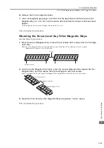
Page 156: ...dure 1 Place the second Magnetic Way in line with and at least 30 mm away from the first Mag netic Way Note Face the Magnetic Ways in same orientation using the locations of the reference marks as a g...

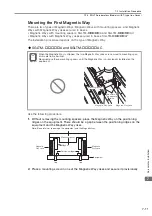
Page 157: ...a Magnetic Way that is longer than the Moving Coil If one Magnetic Way is shorter than the Moving Coil install two Magnetic Ways first and then install the Moving Coil If you will use only one Magnet...

Page 158: ...nting spacers place the Magnetic Way on the positioning ridges on the equipment There should be a gap between the positioning ridges on the equipment and the Magnetic Way yokes Note Be careful not to...

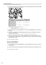
Page 159: ...ws Note Be careful not to let the Magnetic Way yoke slip in the direction of Moving Coil forward movement 6 Remove the mounting spacers If there are Magnetic Way mounting holes in the posi tions where...

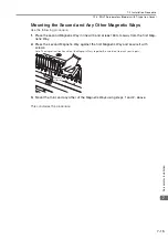
Page 160: ...er is attached 3 Place a thin nonmagnetic sheet in the gap between the Moving Coil and Magnetic Way The sheet must be approximately 0 5 mm thick and we recommend using a plastic sheet An SGLT Moving C...

Page 161: ...come into contact with the Magnetic Ways That there is no foreign matter magnetic material between the magnets 6 Remove the thin nonmagnetic sheet 7 Use a nonmagnetic gap gauge to confirm that the ga...

Page 162: ...ond Magnetic Way in line with and at least 30 mm away from the first Mag netic Way 2 Press the second Magnetic Way against the first Magnetic Way and secure it with screws Note The magnetic attraction...

Page 163: ...area of the heat sink is too small the temperature of the Servomotor may increase abnormally If the operating environment makes it difficult to use a large heat sink or if the ambient oper ating temp...

Page 164: ...otors 8 3 8 2 Mounting Linear Encoders 8 4 8 2 1 Linear Encoders from Heidenhain Corporation 8 4 8 2 2 Linear Encoders from RSF Elektronik GmbH 8 4 8 2 3 Linear Encoders from Renishaw PLC 8 4 8 2 4 Li...

Page 165: ...0 5 mT max SQ47 SQ57 5 mT max Mitutoyo Corporation ST78 A 3 mT max If the linear encoder mounting materials or the Magnetic Way mounting materials are magnetic materials the magnetic field strength ma...

Page 166: ...Model Distance from Magnetic Way X mm Y mm Z mm Z mm SGLFM 20 85 55 85 10 35 100 65 110 10 50 125 80 135 10 1Z 165 95 170 10 SGLFM2 30 85 50 95 10 45 120 75 140 10 90 160 90 175 10 1D 175 90 200 10 Z...

Page 167: ...f the forward direction of the Servomotor and the count up direction of the linear motor do not agree the Servomotor may not operate or it may run out of control Important Motor forward direction U V...

Page 168: ...in the diagram on the left the count is incremented when the scanning head moves to the right Reverse Scanning head Signal cable Forward Mitutoyo Reverse Scanning head Signal cable Forward Mitutoyo I...

Page 169: ...ays adjust the mounting of the scanning head Consult the manufacturer of the linear encoder for the adjustment method Sealed Linear Encoders No adjustment is necessary However you must observe the dim...

Page 170: ...ces and provides related precau tions 9 1 Selecting Cables 9 2 9 1 1 Linear Encoder Cables 9 2 9 1 2 Serial Converter Unit Cables 9 2 9 1 3 Sensor Cables 9 3 9 1 4 Serial Converter Units 9 4 9 2 Wirin...

Page 171: ...m JZSP CLL00 01 E 3 m JZSP CLL00 03 E 5 m JZSP CLL00 05 E 10 m JZSP CLL00 10 E 15 m JZSP CLL00 15 E For linear encoder from Heidenhain Corporation 1 m JZSP CLL30 01 E 3 m JZSP CLL30 03 E 5 m JZSP CLL...

Page 172: ...E SGLFW2 A AS With Polarity Sensor Hall Sensor 1 m JZSP CL2L100 01 E 3 m JZSP CL2L100 03 E 5 m JZSP CL2L100 05 E 10 m JZSP CL2L100 10 E 15 m JZSP CL2L100 15 E SGLFW2 A AT Without Polarity Sensor Hall...

Page 173: ...GLGW coreless models For Stan dard force Magnetic Way 30A050C 250 SGLFW models with F type iron cores 20A090A 017 30A080C 251 20A120A 018 40A140C 252 35A120A 019 40A253C 253 35A230A 020 40A365C 254 50...

Page 174: ...20 mA Typ 160 mA max Signal Resolution 1 256 pitch of input two phase sine wave 1 4 096 pitch of input two phase sine wave Maximum Response Frequency 250 kHz 100 kHz Analog Input Signals 2 cos sin and...

Page 175: ...e or withstand voltage tests 2 When analog signals are input to the Serial Converter Unit they are very weak signals and therefore noise influence on the analog signals affects the Unit s ability to o...

Page 176: ...ble are as thin as 0 2 mm2 or 0 3 mm2 Wire them so that they are not subjected to excessive stress If you secure the cables with cable ties protect the cables with cushioning material If the cable wil...

Page 177: ...degree of flexibility such as twisting and turning or in which the cables themselves must move When you use Standard Cables observe the recommended bending radius given in the following table and perf...

Page 178: ...number of bends while the lead wires are electrically charged for which no cracks or damage that affects the performance of the cable sheathing occur Breaking of the shield wire is not considered Stra...

Page 179: ...rectly to an absolute linear encoder Serial Converter Unit Cable between SERVOPACK connector CN2 and Serial Converter Unit SERVOPACK Linear encoder Not provided by Yaskawa Linear Servomotor Polarity s...

Page 180: ...an connect directly to an absolute linear encoder SERVOPACK Linear encoder Not provided by Yaskawa Polarity sensor hall sensor Sensor Cable between Serial Converter Unit and polarity sensor hall senso...

Page 181: ...n absolute linear encoder SERVOPACK Linear encoder Not provided by Yaskawa Polarity sensor hall sensor Sensor Cable between Serial Converter Unit and polarity sensor hall sensor Serial Converter Unit...

Page 182: ...aintenance inspection and disposal of a Servomotor 10 1 Periodic Inspections 10 2 10 1 1 Linear Servomotor Inspections 10 2 10 1 2 Linear Encoder Inspections 10 3 10 2 Disposing of Servomotors 10 4 Ma...

Page 183: ...technician Failure to observe this caution may result in electric shock or injury Contact your Yaskawa representative for help with failures repairs or part replacement Item Inspection Period Basic I...

Page 184: ...sis tance At least once a year Disconnect the Servomotor from the SERVOPACK and measure the insulation resis tance at 500 V with an insula tion resistance meter Measurement method Mea sure the resista...

Page 185: ...strial waste However local ordinances and national laws must be observed Implement all labeling and warnings as a final product as required CAUTION When you dispose of a Linear Servomotor heat the Mag...

Page 186: ...de changes to some parts Chapter 4 Addition SGLFW2 90A200A L 6 4 Addition Precautions for water cooled models 8 1 Addition SG10 and SQ47 SQ57 September 2014 1 All chapters Corrected mistakes and made...

Page 187: ...awa co th YASKAWA ELECTRIC CHINA CO LTD 22F Link Square 1 No 222 Hubin Road Shanghai 200021 China Phone 86 21 5385 2200 Fax 86 21 5385 3299 www yaskawa com cn YASKAWA ELECTRIC CHINA CO LTD BEIJING OFF...

Reviews: