3.3 External Dimensions
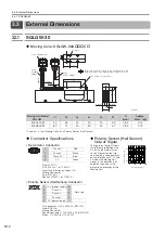
3.3.1 SGLGW-30
3
S
pecification
s
, Rating
s
, and Exter
nal Dimen
s
ion
s
of
SG
L
G
S
ervomotor
s
3-13
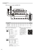
Moving Coils: SGLGW-30A
C
D
*
The mass is for a Moving Coil with a Polarity Sensor (Hall Sensor).
Moving Coil Model
SGLGW-
L1
L2
L3
L4
L5
W
G (Gap)
Approx.
Mass
*
[kg]
30A050C
D
50
48
30
20
20
5.9
0.85
0.14
30A080C
D
80
72
50
30
25
5.7
0.95
0.19
Connector Specifications
Polarity Sensor (Hall Sensor)
Output Signal
•
Servomotor Connector
The figure on the right shows
the relationship between the
Su, Sv, and Sw polarity sen-
sor (hall sensor) output sig-
nals and the inverse power of
each motor phase Vu, Vv,
and Vw when the Moving Coil
moves in the direction indi-
cated by the arrow in the
dimensional drawings of the
Moving Coil.
Extension: SROC06JMSCN169
Pins: 021.423.1020
From Interconnectron GmbH
Mating Connector
Plug: SPUC06KFSDN236
Socket: 020.030.1020
•
Polarity Sensor (Hall Sensor) Connector
Pin connector: 17JE-23090-02 (D8C)-CG
From DDK Ltd.
Mating Connector
Socket connector: 17JE-13090-02 (D8C)A-CG
Studs: 17L-002C or 17L-002C1
2 × #4-40 UNC
s
crew
s
Cable
UL20276,
AWG26
(5.
3
dia.)
(5 dia.)
The Moving Coil move
s
in the direction indicated by the
arrow when current flow
s
in the following pha
s
e
s
equence:
U, V, W.
Cable
UL2517, AWG25
2 × 2 × M4 × 5 (both
s
ide
s
)
Unit: mm
3
22
24
48.5
15
500±50
500±50
L1
L
3
L2
G (Gap)
G (Gap)
17
4 × M4 × 5
L5
L4
1
57
44
W
12
Vu
Vv
Vw
S
u
S
v
S
w
0
180
3
60
540
Electrical angle (°)
Inver
s
e power (V)
3
2
4
6
1
5
1
Phase U
Red
2
Phase V
White
3
Phase W
Blue
4
Not used
−
5
Not used
−
6
FG
Green
9
6
5
1
1
+5 V (power supply)
6
Not used
2
Phase U
7
3
Phase V
8
4
Phase W
9
5
0 V (power supply)
−
−


