4.3 Ratings and Specifications: SGLFW Models
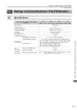
4.3.2 Ratings
4-14
4.3.2
Ratings
*1.
These values are for operation in combination with a SERVOPACK when the temperature of the armature wind-
ing is 100
°
C. The values for other items are at 20
°
C. These are typical values.
*2.
The rated forces are the continuous allowable force values at a surrounding air temperature of 40
°
C with an alu-
minum heat sink of the dimensions given in the following table.
•
Heat Sink Dimensions
•
125 mm
×
125 mm
×
13 mm: SGLFW-20A090A and -20A120A
•
254 mm
×
254 mm
×
25 mm: SGLFW-35A120A and -35A230A
•
400 mm
×
500 mm
×
40 mm: SGLFW-50A200B, 50A380B, and -1ZA200B
•
600 mm
×
762 mm
×
50 mm: SGLFW-1ZA380B
*3.
To externally connect dynamic brake resistor, select hardware option specification 020 for the SERVOPACK.
However, you cannot externally connect dynamic brake resistor if you use the following SERVOPACKs (maxi-
mum applicable motor capacity: 400 W).
•
SGD7S-R70
A020 to -2R8
A020
•
SGD7W-1R6A20A020 to -2R8A20A020
•
SGD7C-1R6AMAA020 to -2R8AMAA020
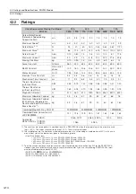
Linear Servomotor Moving Coil Model
SGLFW-
20A
35A
50A
1ZA
090A
120A
120A
230A
200B
380B
200B
380B
Rated Motor Speed
(Reference Speed during
Speed Control)
*1
m/s
5.0
3.5
2.5
3.0
1.5
1.5
1.5
1.5
Maximum Speed
*1
m/s
5.0
5.0
5.0
5.0
5.0
5.0
4.9
4.9
Rated Force
*1, *2
N
25
40
80
160
280
560
560
1120
Maximum Force
*1
N
86
125
220
440
600
1200
1200
2400
Rated Current
*1
Arms
0.70
0.80
1.4
2.8
5.0
10.0
8.7
17.5
Maximum Current
*1
Arms
3.0
2.9
4.4
8.8
12.4
25.0
21.6
43.6
Moving Coil Mass
kg
0.70
0.90
1.3
2.3
3.5
6.9
6.4
12
Force Constant
N/Arms
36.0
54.0
62.4
62.4
60.2
60.2
69.0
69.0
BEMF Constant
Vrms/(m/s)/
phase
12.0
18.0
20.8
20.8
20.1
20.1
23.0
23.0
Motor Constant
N/
7.95
9.81
14.4
20.4
34.3
48.5
52.4
74.0
Electrical Time Constant
ms
3.2
3.3
3.6
3.6
16
16
18
18
Mechanical Time Constant
ms
11
9.4
6.3
5.5
3.0
2.9
2.3
2.1
Thermal Resistance
(with Heat Sink)
K/W
4.35
3.19
1.57
0.96
0.56
0.38
0.47
0.20
Thermal Resistance
(without Heat Sink)
K/W
7.69
5.02
4.10
1.94
1.65
0.95
1.30
0.73
Magnetic Attraction
N
310
460
810
1590
1650
3260
3300
6520
Maximum Allowable Payload
kg
3.2
4.8
8.7
29
33
67
66
78
Maximum Allowable Payload
(With External Regenerative
Resistor and External Dynamic
Brake Resistor
*3
)
kg
3.2
4.8
8.7
29
40
80
82
160
Combined Magnetic Way, SGLFM-
20
A
35
A
50
A
1Z
A
Combined Serial Converter Unit,
JZDP-
-
017
018
019
020
181
182
183
184
Applicable
SERVOPACKs
SGD7S-
1R6A, 2R1F
3R8A
5R5A
120A
200A
SGD7W-
SGD7C-
1R6A
5R5A
−
W


