5.1 Type of Adjustments and Basic Adjustment Procedure
5-5
5
Adjustments
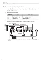
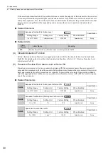
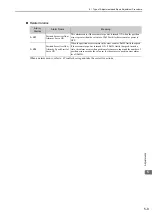
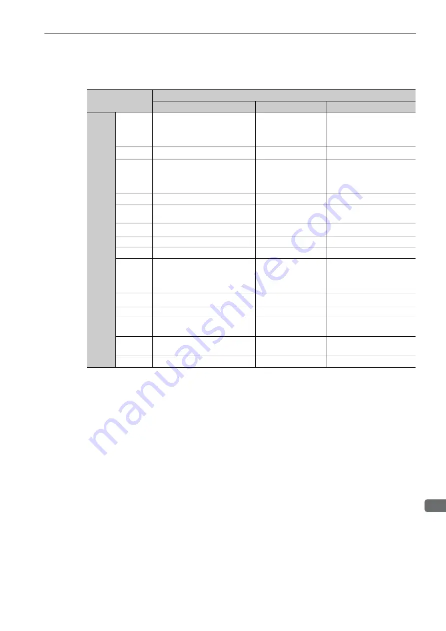
The following signals can be monitored by selecting functions with parameters Pn006 and Pn007.
Pn006 is used for analog monitor 1 and Pn007 is used for analog monitor 2.
∗
Refer to
5.6.1 Switching Gain Settings
for details.
Parameter
Description
Monitor Signal
Unit
Remarks
Pn006
Pn007
n.
00
[Pn007
Factory
Setting]
Motor rotating speed
1 V/1000 min
-1
−
n.
01
Speed reference
1 V/1000 min
-1
−
n.
02
[Pn006
Factory
Setting]
Torque reference
1 V/100% rated torque
−
n.
03
Position error
0.05 V/1 reference unit
0 V at speed/torque control
n.
04
Position amplifier error
0.05 V/1 encoder pulse
unit
Position error after electronic
gear conversion
n.
05
Position reference speed
1 V/1000 min
-1
−
n.
06
Reserved (Do not use.)
−
−
n.
07
Reserved (Do not use.)
−
−
n.
08
Positioning completed
Positioning completed:
5 V
Positioning not com-
pleted: 0 V
Completion indicated by out-
put voltage.
n.
09
Speed feedforward
1 V/1000 min
-1
−
n.
0A
Torque feedforward
1 V/100% rated torque
−
n.
0B
Active gain
*
1st gain: 1 V
2nd gain: 2 V
Gain type indicated by output
voltage.
n.
0C
Completion of position reference
Completed: 5 V
Not completed: 0 V
Completion indicated by out-
put voltage.
n.
0D
Reserved (Do not use.)
−
−

