background image

Installation and Operation Guide SOLECTRIA XGI 1500 (Rev E, 5 Mar. 2021) 


66 of 70 

 Options 

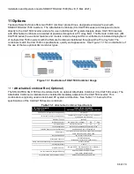
Yaskawa Solectria Solar offers two 1500V combiner product lines, designed exclusively to pair with 
SOLECTRIA XGI 1500 inverters.  The Attachable Combiners (CA-XGI1500 series) are designed to mate 
directly to the XGI 1500 inverter and are for use in distributed PV system designs where XGI 1500 inverters 
with Attachable Combiners are located at positions throughout a PV array field.  The Remote Combiners (CR-
XGI1500 series) have similar features and models, and are designed for a centralized or clustered deployment 
of multiple XGI 1500 inverters with the Remote Combiners distributed throughout the PV array field. The 
combiners match the XGI 1500 in specifications, quality and appearance.  See Figure 11-1 for an illustration of 
the use of the two optional XGI combiner types. 


Figure 11-1


Illustration of XGI 1500 Combiner Usage 


Attachable Combiner Box (Optional) 

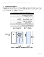
The SOLECTRIA XGI 1500 can be ordered with an optional Attachable Combiner (CA-XGI1500 series). The 
Attachable Combiner is intended to be installed immediately adjacent to the XGI 1500 inverter. This 
combination is typically used in distributed PV system architecture.  See Table 11-1 below for the 
specifications of the CA-XGI1500 series combiners.   

Table 11-1 

Attachable Combiner Specifications 


15A or 20A (fuses included)

25A

30A

16 / 20 / 24 / 26 / 28

20

16

Ungrounded PV Source Circuits Only

Both Positive and Negative Polarities Fused

Enclosure Material, Weight and Rating

Polyester Powder Coated Aluminum

75 lbs (34 kg), NEMA Type 4X 

Surge Protection (Specific Models Only)

Both positive and negative polarities 

Standard Warranty

5 Years

Overall Dimensions

Height: 29.5 in. (750 mm) 

|

 Width: 15 in. (380 mm)

Depth: 10.6 in. (260 mm)

Mounting Orientation

Vertical orientation

located adjacent to the XGI 1500 inverter 

Safety Certification & Listing / Certification Agency

UL 1741 / Intertek

DC Disconnect

2-Pole DC Disconnect (On the XGI 1500 Inverter) Positive 

and Negative Poles Switched, 250A

Temperature Range

-40°F to 122°F (-40C to +50C)

Fuse Rating Options

Fused Positions

Fuse Configuration

Input PV Source Circuit Configuration

PV Ourput Circuit Wire Compatibility

Compression Terminal:  1 conductor, 1/0 - 750 kcmil

2 conductors, 1/0 - 600 kcmil 

Maximum Voltage

1500 VDC

ATTACHABLE COMBINER 
CA-XGI1500 Series

1500V STRING COMBINERS

EXCLUSIVELY FOR USE WITH XGI1500 INVERTERS

PV Source Circuit Input Wire Compatibility

14 - 4 AWG

Summary of Contents for SOLECTRIA XGI 1500 Series

Page 1: ...ial 1500VDC String Inverter SOLECTRIA XGI 1500 Installation and Operation Guide Models XGI 1500 125 125 UL XGI 1500 125 150 UL XGI 1500 150 166 UL XGI 1500 166 166 UL XGI 1500 125 125 3S XGI 1500 166...

Page 2: ...nsformer Configuration 19 Equipment Grounding 20 AC Connections 22 AC Breaker Specifications 23 DC Connections 24 DC Connection Using the XGI Remote or Attachable Combiner 25 DC Connection Using the X...

Page 3: ...ates 50 Automatic Remote Firmware Updates 50 Manual Firmware Updates Locally 50 Manual Firmware Updates Remote Server 50 Manual Firmware Updates Remote Access Portal 50 Communication Commissioning 52...

Page 4: ...y or death CAUTION indicates a hazardous situation which if not avoided will result in minor or moderate injury NOTICE indicates a hazardous condition which if not avoided could result in equipment wo...

Page 5: ...contact components with hazardous voltage and energy Use proper safety equipment including Personal Protective Equipment PPE when de energizing the unit De energize the unit wait 5 minutes and verify...

Page 6: ...Ready Yellow On Inverter is initialized and ready to operate Off Inverter is not ready to operate Network and Communication Yellow On Network and communication services are working properly Off Netwo...

Page 7: ...logy o Max efficiency 99 0 o CEC efficiency 98 5 Grid adaptability o Supports multiple grid standards o Certified to UL1741SA for CA Rule 21 compliance o Adjustable reactive power o Adjustable power f...

Page 8: ...AC output o Internal ambient temperature o IGBT module temperature 2 1 3 Communication Overview Users can communicate with the SOLECTRIA XGI 1500 using a Wi Fi enabled smart device such as a laptop t...

Page 9: ...Installation and Operation Guide SOLECTRIA XGI 1500 Rev E 5 Mar 2021 9 of 70 2 1 4 Inverter Features Figure 2 3 SOLECTRIA XGI 1500 Inverter Features Front Left Right Side Right and Bottom Bottom...

Page 10: ...of the inverter it is recommended to mount the inverter out of the direct sunlight Inverter Facing Direction It is recommended to install the inverter facing north to minimize direct sun exposure Fig...

Page 11: ...er from its crate and properly dispose of the packaging material 2 Secure the inverter to the structure carefully observing the lifting hazard below Lifting Heavy Object Hazard Proper lifting techniqu...

Page 12: ...ure 3 4 Ensure that the strut channel structure is capable of supporting 270 lbs 122 kg plus an effective safety margin Structural integrity of the strut structure is the responsibility of the install...

Page 13: ...bolts not provided to connect the bottom brackets to the strut channel Figure 3 3 Mounting Holes Rear View Attach the inverter with its mounting brackets in place to the strut channel as shown in Fig...

Page 14: ...the holes provided in the top face of the upper brackets and two more through the front face of the lower bracket Figure 3 5 Inverter Mounted to Strut Channels Back View Upper Image and Top View Lowe...

Page 15: ...ottom of the inverter Remove the gland plate before drilling or punching holes to prevent metal debris from entering the inverter enclosure Re attach the gland plate to install conduit fittings and co...

Page 16: ...ns are complete replace all 10 screws and torque to 25 in lbs 2 8 Nm All modifications to the conduit panel must be contained within the region shown in Figure 3 8 For inverters paired with the attach...

Page 17: ...Installation and Operation Guide SOLECTRIA XGI 1500 Rev E 5 Mar 2021 17 of 70 Figure 3 8 Removable Conduit Panel Entry Locations...

Page 18: ...on and Operation Guide SOLECTRIA XGI 1500 Rev E 5 Mar 2021 18 of 70 Figure 3 9 DC Conduit Hole Location for Inverters Paired with Attachable Combiners Figure 3 10 Conduit Hole Location for Attachable...

Page 19: ...rter must be connected to an isolation transformer provided by the customer that has a grounded Wye configuration on the inverter side see Figure 3 11 The neutral of this transformer must be grounded...

Page 20: ...m On the exterior of the inverter is an M6 threaded insert Figure 3 13 Torque this customer supplied fastener to 39 in lbs 4 4N m Figure 3 13 Ground Connection Inside and Outside Inverter Table 3 1 G...

Page 21: ...Installation and Operation Guide SOLECTRIA XGI 1500 Rev E 5 Mar 2021 21 of 70 2 to 1 0 AWG 33 6 to 53 5 mm2 2 to 1 0 AWG 33 6 to 53 5 mm2 2 to 1 0 AWG 33 6 to 53 5 mm2 2 to 1 0 AWG 33 6 to 53 5 mm2...

Page 22: ...53 5 mm2 4 to 1 0 AWG 21 1 to 53 5 mm2 2 to 1 0 AWG 33 6 to 53 5 mm2 Electric Shock Hazard Components with hazardous voltage and energy will electrocute the operator Ensure AC power doesn t flow into...

Page 23: ...ayer is a poor conductor which could lead to thermal issues production loss or damage to the inverter Clockwise Phase Rotation Ensure the inverter is installed with a clockwise phase rotation A counte...

Page 24: ...ts multiplied by 1 25 must be less than 320 A Equation 3 2 1 5 1 66 2 0 at STC 3 1 1 25 500A 3 2 DC AC Ratio and Isc Requirements Both the DC AC ratio and Isc limit requirements must be met Failure to...

Page 25: ...r 28 positions 25 A 20 positions 30 A 16 positions Fuse Configuration Both Poles Fused Switch Configuration Both Poles Switched Open Fuse Holders Verify the absence of DC voltage and current when inse...

Page 26: ...mm2 4 0 AWG 107 mm2 250 kcmil 127 mm2 300 kcmil 152 mm2 Maximum Wire Size Aluminum 500 kcmil 240 mm2 500 kcmil 240 mm2 500 kcmil 240 mm2 500 kcmil 240 mm2 For the DC connections use compression lugs w...

Page 27: ...Confirm proper polarity of connections with a multimeter The PV Output Circuit Wiring Harness Assembly is designed to simplify the field interconnection of the Combiner and the XGI 1500 inverter The W...

Page 28: ...the conduit coupling to secure the conduit assembly in place in both enclosures 4 Proceed to terminate the PV Output Circuit conductors to the lugs noting carefully the polarity markings on the termin...

Page 29: ...at will damage critical components IMPORTANT Risk of condensation is greatest when inverters are left inoperative in the time between installation and beginning daily normal operation To manage moistu...

Page 30: ...back on the inverter Use a 3 Phillips head torque driver to tighten the cover screws to 40 in lbs 4 5 N m Refer to Figure 3 6figure Torque to Specified Value Overtightening the screws may warp the co...

Page 31: ...uits from underground circuits are appropriately sealed Electrical Check Verify that the AC circuit breaker is appropriately sized Refer to Section 0 Test whether the AC voltage is within 5 of nominal...

Page 32: ...perly configured and compliant with the interconnection agreement Connect a power quality analyzer oscilloscope or other digital voltage measurement device on the inverter side of the PV system discon...

Page 33: ...ctors must utilize Ethernet Cat 6 Shielded cable The shield must be terminated properly to provide connection with ground INFO Ethernet Cat 6 Shielded Cable Solar PV inverters create an electrically n...

Page 34: ...s 50 inverters When using star or mixed network configurations the maximum number of inverters from one end of a daisy chain to the end of any other daisy chain within a given Cluster must not exceed...

Page 35: ...Installation and Operation Guide SOLECTRIA XGI 1500 Rev E 5 Mar 2021 35 of 70 Figure 5 2 Mixed network...

Page 36: ...built in firewall that is automatically established on the Gateway Inverter after receiving an IP address assigned via a DHCP or through manual static IP configuration This act of establishing a fire...

Page 37: ...e employed in order for the third party DAS to reach each inverter as an Endpoint Device 1 Port forwarding 2 Static Routing discussed in detail in Section 5 7 Be sure to consult with the monitoring pr...

Page 38: ...vider before implementing When Port Forwarding is implemented a third party DAS can address each inverter using the Gateway Inverter External IP and the specified port for the inverter with the cluste...

Page 39: ...ternal device DAS Up to two IP Subnet pairs can be entered on each gateway NOTICE CYBER SECURITY Configuring an entire IP subnet will not only allow the desired DAS device but would also enable all th...

Page 40: ...ndpoint Device by a DAS or other external device using the Inverter Cluster IP address and port 502 for example 10 78 125 31 502 Inverter Cluster IPs can be configured see Section 5 11 5 10 1 Static R...

Page 41: ...IP on the Modbus Access Configuration page see Figure 5 8 The method of entering static routing rules varies depending on the device or operating system for more information work with your IT professi...

Page 42: ...ts The SOLECTRIA XGI has two interchangeable Ethernet Ports These connections are located in the right hand compartment within the Wire Box 5 12 1 Weather Station Connection Optional Only use weather...

Page 43: ...r within a given Cluster INFO Inter Inverter Communication Over Ethernet Only All XGI inverters are equipped with a WiFi antenna which is used to tether a smart device to the inverter or Cluster Inver...

Page 44: ...1 Connecting to the Inverter Ethernet To access the inverter using Ethernet connect an Ethernet cable from the laptop to the inverter The Ethernet port is located inside the wiring box see Figure 3 7...

Page 45: ...e XGI provides a strong WiFi signal with 75ft and direct line of site Ensure the WiFi antenna is connected to the inverter Try closing your web browser and re opening a new session Check to make sure...

Page 46: ...nverter has an inverter issue and cannot produce power Inverter Warning This indicates that the inverter has an issue but can produce power In the sample inverter list in several nodes are worth notin...

Page 47: ...he inverter status icons will give their current state as shown in Figure 6 3 Current Status with Network and Communication Working and Maintenance with an Event The menu button is located in the uppe...

Page 48: ...CASE SENSITIVE ADMIN SolectriaSolar The inverter will log the user out automatically after it is idle for 30 minutes 6 2 6 Changing Settings Changing settings or configurations in the GUI is easy and...

Page 49: ...Logs Edit Inverter List Firmware Update First Time Start Wizard AC Voltage and Frequency Trip Settings Power Limiting Power Factor Control Reactive Power Control Volt VAr Volt Watt Freq Watt Ramp Rate...

Page 50: ...has stabilized but prior to peak production reducing lost revenue Having the Enable Automatic Remote Firmware update unchecked is not recommended as product improvements may have occurred since the p...

Page 51: ...Installation and Operation Guide SOLECTRIA XGI 1500 Rev E 5 Mar 2021 51 of 70 Figure 7 1 Firmware Update...

Page 52: ...d on for a minimum of 10 minutes Startup Wizard Run the Startup Wizard by logging into one of the inverters and selecting Startup Wizard from the main menu Name the Inverters Enter a name for each inv...

Page 53: ...te that some of these events can create a hazardous situation indicated by DO NOT TOUCH in Table 9 1 Critical Event Codes Ground Fault Hazard Inverter enclosure is an electrical hazard DO NOT TOUCH an...

Page 54: ...has been detected Insolation resistance between the DC conductors and ground is below the allowable limit Check the array for an unintentional reference to ground DO NOT TOUCH any equipment including...

Page 55: ...Inspect the AC conductors for damage If AC voltage is present and the inverter will not grid connect contact Technical Support 4 Open Phase Detected Open AC phase condition has been detected Using a C...

Page 56: ...oltage 3 Detected AC low voltage region 3 detected Using a CAT III multi meter verify the AC voltage If there is a discrepancy of greater than 2 between the measured results and the voltage reported b...

Page 57: ...r network 31 Invalid Configuration Request An external request to adjust setting beyond the allowable limits Check to make sure the value being entered is acceptable and re enter 32 Reserved 9 1 3 Inf...

Page 58: ...he wiring portion of the inverter after the inverter has been running for at least an hour Refer to Figure 7 1 1 Allow the inverter to run for at least an hour above 50 power before performing thermog...

Page 59: ...e inverter 9 2 2 Cleaning the Fans and Cooling Plenum The XGI 1500V inverter has three fans on the right hand side of the enclosure These fans are protected with finger guards Over time these guards m...

Page 60: ...o collect in the cooling plenum on the heatsinks and inductors located in this section of the inverter A removable panel located at the rear of the inverter provides access for cleaning Figure 9 3 Rea...

Page 61: ...ter to the OFF position 2 Remove the 11 screws from the rear access panel and set aside Figure 9 4 Rear Access Panel Removed 3 Use a vacuum with a non metallic nozzle to remove the debris from air ple...

Page 62: ...ck feed 0 A Open Circuit Strike Voltage 920 VDC Synchronization Inrush Current 12 ARMS Output Power Factor Unity 0 99 Adjustable from 0 80 to 0 80 Grid Type 3 Phase Wye with Ground and Neutral Nominal...

Page 63: ...e 1 Clearing Time 0 2 s Clearing Time Adjustable Up to and Including 0 1 s V 45 0 16 s 0 16 s 45 V 60 1 0 s 11 s 60 V 88 2 0 s 21 s 88 V 110 No trip No trip 110 V 120 1 0 s 13 s f 120 0 16 s 0 16 s Ta...

Page 64: ...5 Normal Temperature Ranges Ambient Temperature Range 40 F to 140 F 40 C to 60 C Derating Temperature 113 F 45 C Storage Temperature Range 40 F to 167 F 40 C to 75 C Figure 10 3 Derating with Temperat...

Page 65: ...Guide SOLECTRIA XGI 1500 Rev E 5 Mar 2021 65 of 70 Figure 10 4 Derating with Altitude 0 10 20 30 40 50 60 70 80 90 100 0 0 0 5 1 0 1 5 2 0 2 5 3 0 3 5 4 0 4 5 Percent of Full Power Altitude km of Rat...

Page 66: ...XGI 1500 inverter This combination is typically used in distributed PV system architecture See Table 11 1 below for the specifications of the CA XGI1500 series combiners Table 11 1 Attachable Combine...

Page 67: ...ar 2021 67 of 70 Figure 11 2 SOLECTRIA XGI 1500 with the Attachable Combiner Box Figure 11 3 SOLECTRIA XGI 1500 Attached Combiner Box 10 6 in 260mm 15 in 380mm 29 5 in 750mm UPPER MOUNTING BRACKET LOW...

Page 68: ...Aluminum 85 lbs 38 6 kg NEMA Type 4X Height 29 5 in 750 mm Width 18 1 in 460 mm Depth 11 in 280 mm Enclosure Material Weight and Rating Safety Certification Listing Certification Agency Standard Warra...

Page 69: ...please visit http solectria com support documentation warranty information grid tied inverter warranty letter Yaskawa Solectria Solar Contact Information Table 12 1 Yaskawa Solectria Solar Contact Inf...

Page 70: ...Installation and Operation Guide SOLECTRIA XGI 1500 Rev E 5 Mar 2021 70 of 70 Authorization to Mark...

Reviews: