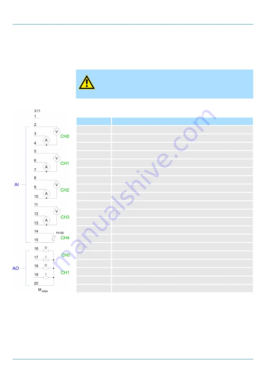
6.4 Analog part
The analog part consists of 4 input, 2 output channels and 1 Pt100 channel. 10byte input
and 4byte output data of the process image are used by the analog part. The channels of
the module are galvanically separated from the bus via DC/DC transducer and
optocouplers.
CAUTION!
Temporarily not used analog inputs with activated channel must be con-
nected to the concerning ground. To avoid measuring errors, you should
connect only one measuring type per channel.
Pin assignment X11: AIO
Pin
Assignment
1
not connected
2
Voltage measurement channel 0
3
Current measurement channel 0
4
Ground channel 0
5
Voltage measurement channel 1
6
Current measurement channel 1
7
Ground channel 1
8
Voltage measurement channel 2
9
Current measurement channel 2
10
Ground channel 2
11
Voltage measurement channel 3
12
Current measurement channel 3
13
Ground channel 3
14
Pt 100 channel 4
15
Pt 100 channel 4
16
Voltage output channel 0
17
Current output channel 0
18
Voltage output channel 1
19
Current output channel 1
20
Ground AO channel 0 and 1
Status indicator X11: AIO
From the analog part no LEDs are controlled.
313-5BF23
VIPA System 300S
+
Deployment I/O periphery
Analog part
HB140 | CPU-SC | 313-5BF23 | en | 19-01
92


