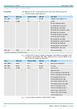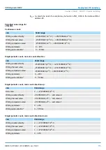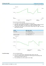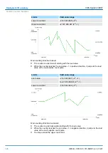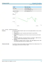
Here there are the following adjustment possibilities:
n
Hardware interrupt
–
A hardware interrupt may be optionally triggered on the rising or falling edge of an
input. There are no hardware interrupts available at input I+2.0 ... I+2.7 of the
CPU 313-5BF23.
A diagnostic interrupt is only supported together with hardware interrupt lost.
Select with the arrow keys the input and activate the desired hardware interrupt.
n
Input delay
–
The input delay may be configured per channel in groups of four. Please note that
in the parameter window only the value 0.1ms may be set. At the other values
0.35ms is internally used for input delay.
There are no parameters for the digital output channels.
6.6 Counter
6.6.1 Counter - Fast introduction
The CPU 313-5BF23 has in-/outputs, which may be used for technological functions
respectively as standard periphery. Technological functions and standard I/O may be
used simultaneously with appropriate hardware. Read access to inputs used by techno-
logical functions is possible. Write access to used outputs is not possible. The parameter-
ization of the corresponding channel is made in the hardware configurator by means of
the
Count
submodule of the CPU 313C from Siemens. Now the following technological
functions at 3 channels are at the disposal:
n
Continuous count, e.g. for position decoding with Incremental encoder
n
Single count, e.g. for unit decoding to a maximum limit
n
Periodical count, e.g. for applications with repeated counting operations
Independent of the number of activated counters for the CPU 313-5BF23 the maximum
frequency amounts to 30kHz.
The controlling of the appropriate modes of operation is made from the user program by
the SFB COUNT (SFB 47).
The counter signal is detected and evaluated during counting operation. Every counter
occupies one double word in the input range for the
counter register
. In the operating
modes "single count" and "periodical count" an end respectively start value may be
defined according to the counting direction up respectively down. Each counter has
parameterizable additional functions as gate function, latch function, comparison value,
hysteresis and hardware interrupt. Each counter parameter may be set by the
Count
sub-
module of the Siemens CPU 313C. Here is defined among others:
n
Interrupt behavior
n
Max. frequency
n
Counter mode respectively behaviour
n
Stat, end, comparison value and hysteresis
1.
Start the Siemens SIMATIC Manager with your project and open the hardware con-
figurator.
2.
Place a profile rail.
3.
Configure at slot 2 the corresponding CPU from Siemens CPU 313C.
Inputs
Outputs
Overview
Pin assignment
Preset respectively param-
eterize counter
Parameterization
VIPA System 300S
+
Deployment I/O periphery
Counter > Counter - Fast introduction
HB140 | CPU-SC | 313-5BF23 | en | 19-01
107


