7.
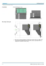
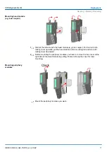
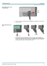
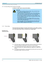
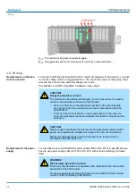
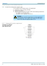
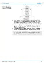
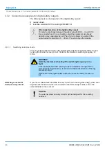
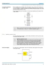
Turn all the locking lever downward again.
8.
Plug again the electronic module, which you have removed before.
3.6 Wiring
To be able to fulfil the standard EN 60 204-1 (electrical equipment of machines), you have
to use the cables, which are suggested there. The connectors may not drop away, other-
wise the risk of short-cuts, external voltages etc. exists.
Pay attention to a EMC-compatible installation of the cables.
CAUTION!
Danger by electrical current!
The module can be destroyed/damaged, if you do not ensure the require-
ments for the electrical connection of the module.
–
Make sure that the connected loads specified in the technical data
are kept and that the connections are made in accordance with the
specifications.
–
Prevent a short-circuit between inputs and outputs. In the case of a
short-circuit between inputs and outputs the electronic module can be
destroyed.
CAUTION!
Please regard in particular that electromechanical sensors (safety switch-
gears) are supplied with suitable clock pulses for short circuit detection.
Electromechanical switches must correspond to the requirements in
accordance with IEC 60947-5-1.
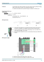
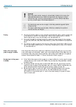
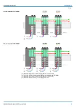
For the adherence to the NAMUR recommendation NE 21 IEC 61131-2 and EN 298 you
have to use power supply units (AC 230V / DC 24V) with a mains buffering of at least
20ms.
WARNING!
Risk of injury by electric current!
There may only devices be connected to the controller, which have a safe
separation of the 230V power.
The power supply to generate 24V power must correspond to the require-
ments for PELV according to EN 60204-1.
Requirements on the elec-
trical connection
Requirement to the power
supply
VIPA System SLIO
Deployment
Wiring
HB300 | SM-S | 02x-1SD10 | en | 20-02
84


