background image

Hardware description

2.1  Safety information for users

VIPA modules make use of highly integrated components in MOS-

Technology. These components are extremely sensitive to over-vol-

tages that can occur during electrostatic discharges. The following

symbol is attached to modules that can be destroyed by electrostatic

discharges.

The Symbol is located on the module, the module rack or on packing

material and it indicates the presence of electrostatic sensitive equip-

ment. It is possible that electrostatic sensitive equipment is destroyed

by energies and voltages that are far less than the human threshold

of perception. These voltages can occur where persons do not dis-

charge themselves before handling electrostatic sensitive modules

and they can damage components thereby, causing the module to

become inoperable or unusable. Modules that have been damaged

by electrostatic discharges can fail after a temperature change,

mechanical shock or changes in the electrical load. Only the conse-

quent implementation of protection devices and meticulous attention

to the applicable rules and regulations for handling the respective

equipment can prevent failures of electrostatic sensitive modules.

Modules must be shipped in the original packing material.

When you are conducting measurements on electrostatic sensitive

modules you should take the following precautions:

n

Floating instruments must be discharged before use.

n

Instruments must be grounded.

Modifying electrostatic sensitive modules you should only use sol-

dering irons with grounded tips.

CAUTION!

Personnel and instruments should be grounded when

working on electrostatic sensitive modules.

2.2  Properties

The VIPA Touch Panel allows you to visualize and alter operating

states and recent process values of a connected PLC. The Touch

Panel is a compact and modular embedded PC based on Windows

Ò

CE. Besides the extensive Windows

Ò

 CE functions the Touch Panel

offers varied communication possibilities. Here the Touch Panel can

simply be configured, controlled and remoted. By including a select-

able HMI/SCADA runtime the Touch Panel is particularly suitable for

monitoring and controlling of process cycles.

Handling of electro-

static sensitive modules

Shipping of modules

Measurements and

alterations on electro-

static sensitive modules

General

VIPA HMI

Hardware description

Properties

HB160 | TP-ECO | 62P-NHC0 | GB | 16-02


9

Summary of Contents for VIPA TP 615LC

Page 1: ...TP ECO 62P NHC0 Manual HB160 TP ECO 62P NHC0 GB 16 02 VIPA HMI Touch Panel TP615LC ...

Page 2: ...62P NHC0_000_TP615LC 4 GB 2016 VIPA GmbH Ohmstr 4 91074 Herzogenaurach Telephone 49 9132 744 0 Fax 49 9132 744 1864 Email info vipa com Internet www vipa com ...

Page 3: ...ger 31 3 5 Connection to a PLC system 33 3 6 Operating system WindowsÒ Embedded CE 6 0 Core 34 3 6 1 General 34 3 6 2 Structure 36 3 7 Integrated Server 40 3 7 1 General 40 3 7 2 ftp server 41 3 7 3 VNC server 42 3 8 Access to the network resources 43 4 Deployment under Windows CE 6 0 Prof 45 4 1 Installation 45 4 2 Installation of the optional MPI PROFIBUS DP interface 46 4 3 Commissioning 48 4 3...

Page 4: ...he EMC equitable assembly of installa tions 68 5 2 EMC equitable assembly 70 5 3 EMC equitable cabling 71 5 4 Special precautions providing high noise immunity 74 5 5 Checklist for the EMC compliant installation of control lers 76 VIPA HMI Table of contents HB160 TP ECO 62P NHC0 GB 16 02 4 ...

Page 5: ...com Every effort has been made to ensure that the information contained in this document was complete and accurate at the time of publishing Nevertheless the authors retain the right to modify the information This customer document describes all the hardware units and functions known at the present time Descriptions may be included for units which are not present at the customer site The exact sco...

Page 6: ...074 Herzogenaurach Germany Telefax 49 9132 744 1204 EMail documentation vipa de Contact your local VIPA Customer Service Organization representa tive if you encounter problems with the product or have questions regarding the product If you are unable to locate a customer service centre contact VIPA as follows VIPA GmbH Ohmstraße 4 91074 Herzogenaurach Germany Tel 49 9132 744 1150 Hotline EMail sup...

Page 7: ... Safety information The Touch Panels are constructed and produced for n VIPA CPUs 01x 11x 21x 31x 51x and S7 300 400 from Sie mens n communication and process control n industrial applications n operation within the environmental conditions specified in the technical data n installation into a cubicle DANGER This device is not certified for applications in in explosive environments EX zone The man...

Page 8: ... carried out when the system has been disconnected from power Installation and hardware modifications only by prop erly trained personnel The national rules and regulations of the respective country must be satisfied installation safety EMC National rules and regulations apply to the disposal of the unit Disposal VIPA HMI General Safety information HB160 TP ECO 62P NHC0 GB 16 02 8 ...

Page 9: ... regulations for handling the respective equipment can prevent failures of electrostatic sensitive modules Modules must be shipped in the original packing material When you are conducting measurements on electrostatic sensitive modules you should take the following precautions n Floating instruments must be discharged before use n Instruments must be grounded Modifying electrostatic sensitive modu...

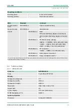
Page 10: ...PI PROFIBUS DP interface optional n Robust aluminium case n Display resolution 1024 x 768 768 x 1024 n Battery backed clock n Resistive analog touch screen n Easy mounting via 10 mounting clips n Protection class IP65 frontal Order data Type Order number Description TP 615LC 62P NHC0 15 TFT color RS232 RS232 RS422 RS485 USB A 2x Ethernet RJ45 MPI PROFIBUS DP interface 961 0MP0 MPI PROFIBUS DP inte...

Page 11: ...1 4 RJ45 jack for Ethernet communication LAN2 5 RS232 interface COM 1 6 RS232 RS422 RS485 interface COM 2 7 MPI PROFIBUS DP interface COM 3 optional 8 Slot for DC 24V voltage supply 9 Display with touch sensitive area touch screen Front view VIPA HMI Hardware description Structure Overview HB160 TP ECO 62P NHC0 GB 16 02 11 ...

Page 12: ...thernet interfaces cannot be used as a Switch 1 RS232 interface COM 1 2 RS232 RS422 RS485 interface COM 2 3 MPI PROFIBUS DP interface COM 3 optional 4 Slot for DC 24V voltage supply Please regard that the Touch Panel always has to be sup plied with external voltage Side view Bottom view VIPA HMI Hardware description Structure Overview HB160 TP ECO 62P NHC0 GB 16 02 12 ...

Page 13: ...2 3 2 Interfaces VIPA HMI Hardware description Structure Interfaces HB160 TP ECO 62P NHC0 GB 16 02 13 ...

Page 14: ...25 pin SubD female RS232 RS422 RS485 interface VIPA HMI Hardware description Structure Interfaces HB160 TP ECO 62P NHC0 GB 16 02 14 ...

Page 15: ...at these two Ethernet interfaces cannot be used as a Switch Using the Host USB A interface USB mouse keyboard stick or USB hard discs can be connected The Touch Panel has got an integrated power supply The power supply has to be provided with DC 24V 20 4 28 8V For this you find an according DC 24V slot at the back The power supply is pro tected against inverse polarity and overcurrent RS232 interf...

Page 16: ...of WindowsÒ CE this memory is listed as Flashdisk at My Device The connection of USB sticks and USB drives by use of the Host USB A interface is supported by the Touch Panel After connection the storage media is listed as Hard Disk at My Device At the back of the Touch Panel there are the card slots for memory cards At this slot you may plug storage modules of the type SD The card may be plugged a...

Page 17: ...only guaranteed when the following is observed Material thickness at the mounting cut out 2 5 6mm The deviation from the plane for the panel cut out is 0 5mm This condition must be fulfilled for the mounted HMI device Permissible surface roughness in the area of the seal 120µm friction coefficient 120 15 62P NHC0 VIPA HMI Hardware description Dimensions HB160 TP ECO 62P NHC0 GB 16 02 17 ...

Page 18: ...e process level electrically isolated Insulation resistance Insulation voltage to reference earth Inputs outputs AC DC 50V test voltage AC 500V Protective measures against short circuit Environmental conditions to EN 61131 2 Climatic Storage transport EN 60068 2 14 25 70 C Operation Horizontal installation EN 61131 2 0 60 C Vertical installation EN 61131 2 0 60 C Air humidity EN 60068 2 30 RH1 wit...

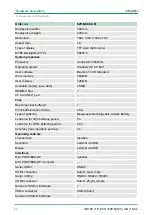
Page 19: ...0V 80 AM 1kHz EN 61000 4 4 Burst degree of severity 3 EN 61000 4 5 Surge installation class 3 Due to the high energetic single pulses with Surge an appropriate external protective circuit with lightning protection elements like conductors for lightning and overvoltage is necessary 2 6 Technical data 2 6 1 62P NHC0 DH Order no 62P NHC0 DH Type Touch Panel TP 615LC Display Display size diagonal 15 D...

Page 20: ...uchscreen resistive Keyboard external via USB Mouse external via USB Interfaces MPI PROFIBUS DP optional MPI PROFIBUS DP connector Serial COM1 RS232 COM1 connector Sub D 9 pin male Serial COM2 RS232 RS422 RS485 COM2 connector Sub D 25 pin female Number of USB A interfaces 1 USB A connector USB A host Number of USB B interfaces USB B connector Number of ethernet interfaces 2 Ethernet Ethernet 10 10...

Page 21: ...t side IP 65 Protect type back side IP 20 Dimensions Front panel 400 mm x 310 mm x 6 mm Rear panel 367 mm x 289 mm x 50 mm Installation cut out Width 368 mm Height 290 mm Minimum 2 5 mm Maximum front panel thickness 6 mm Weight 4900 g Environmental conditions Operating temperature 0 C to 50 C Storage temperature 20 C to 60 C Certifications UL certification yes KC certification 2 6 2 62P NHC0 CB Or...

Page 22: ...d ü Clock buffered period min 26 w Type of buffering Manganese Rechargeable Lithium Battery Load time for 50 buffering period 5 h Load time for 100 buffering period 24 h Accuracy max deviation per day 2 s Operating controls Touchscreen resistive Keyboard external via USB Mouse external via USB Interfaces MPI PROFIBUS DP optional MPI PROFIBUS DP connector Serial COM1 RS232 COM1 connector Sub D 9 pi...

Page 23: ... W Status information alarms diagnostics Supply voltage display none Mechanical data Housing Protection type Material aluminum galvanized steel Mounting mounting clips Protect type front side IP 65 Protect type back side IP 20 Dimensions Front panel 400 mm x 310 mm x 6 mm Rear panel 367 mm x 289 mm x 50 mm Installation cut out Width 368 mm Height 290 mm Minimum 2 5 mm Maximum front panel thickness...

Page 24: ...Order no 62P NHC0 CB UL certification yes KC certification VIPA HMI Hardware description Technical data 62P NHC0 CB HB160 TP ECO 62P NHC0 GB 16 02 24 ...

Page 25: ...lation of the panel 4 mounting clips and a small hex agon socket key are required 1 Push the operator panel 3 from the front side into the front panel cutting 1 until it touches the panel with the seal 2 2 Put the mounting clips 4 on all four sides of the panel into the openings The screws should point in the direction of the front panel 3 Screw the screws from the other side with the hexagon sock...

Page 26: ...n the corresponding ESD packaging 1 Remove the cover plate of the COM3 port by removing the screws and pulling the plate 2 For installation insert the interface module into the opening Push the interface module in the device until the holding plate fits to the housing Here the interface module is put into the right position by 2 inner guide rails Installation VIPA HMI Deployment under Windows CE 6...

Page 27: ...llation the interface module is automatically recognized and can be configured 1 Remove the screws 2 Push the holding plate from the lugs Use a screwdriver by inserting it gently between the housing and holding plate 3 Pull the interface module out of the device 4 Reinstall the cover plate Demounting VIPA HMI Deployment under Windows CE 6 0 Core Installation of the optional MPI PROFIBUS DP interfa...

Page 28: ...er As soon as the Touch Panel is provided by power supply the VIPA Startup Manager will be loaded At the first startup of the VIPA Startup Manager the following start screen appears There is a button on the initial screen with a counter which counts backwards If you click on this button within this time you may return to the selection menu If the time expires the project will start auto matically ...

Page 29: ...t image is not suited for your panel an error massage appears If the image is suited for your panel in the following mes sage the current installed image version and the new selected image version are listed 1 Click on Make Image Update to execute the update This can take a few seconds 2 In the following window click on Finish to end the update ð Then the display gets dark 3 Switch the power suppl...

Page 30: ...conds are default Via Rotation the orientation of the panel can be changed Via Program start with you can add programs which have to start automatically 1 Select start and assign a name for the program 2 Upload your program with 3 You may optionally set parameters 4 Exit with Finish VIPA HMI Deployment under Windows CE 6 0 Core Commissioning VIPA Startup Manager HB160 TP ECO 62P NHC0 GB 16 02 30 ...

Page 31: ...anel 62P NHC0 the directory VIPA and the file AutoRun Maker cfg is necessary of the following zip file n 62P NHC0 _install_SD_Card_Vxxx zip Before the installation can be established you have to stop all the running programmes This also applies to pro grammes which are running in the background such as the transport service of Movicon CEUploadServer exe 1 Call www vipa com 2 Click Service Support ...

Page 32: ...After start up the following window appears 7 Click Make ð All the necessary files are copied and the registry is accord ingly adjusted The progress is displayed in a new window VIPA HMI Deployment under Windows CE 6 0 Core Installation Movicon and Startup Manager HB160 TP ECO 62P NHC0 GB 16 02 32 ...

Page 33: ...to the Touch Panel via a connection that you ve entered before Via the at the Touch Panel pre installed run time version of the HMI SCADA project engineering platforms your project is run able By using the according communication driver the Touch Panel sup ports connecting options to the PLC via field bus and Ethernet During operation your operating device communicates with the according PLC and r...

Page 34: ...ating system WindowsÒ CE 6 0 Core is a WindowsÒ operating system reduced to the absolute essentials with mouse operation touch screen that requires only small hardware resources n ftp and VNC server n Registry Editor n USB keyboard driver n VIPA Startup Manager Please note that for the deployment of WindowsÒ CE a profound knowledge of operating WindowsÒ is assumed Here are only shown the differenc...

Page 35: ...ing that selects the touched objects The windows may be moved via the head bar Here you may also find the OK button to confirm entries and the X button for exiting the dialog You may not exit WindowsÒ By switching the power supply off and on again you may restart WindowsÒ Before a reboot you should always save your data res close all running applications to avoid data loss Please note that changes...

Page 36: ... like e g applications system settings file browser etc 2 Open applications For every open application a button is to be found in the task bar There is no button for minimizing The switch between the appli cations is performed via this buttons 3 Network connection As soon as your Touch Panel is connected via Ethernet you can see here the Ethernet address If there is no connection via Ethernet the ...

Page 37: ...imple mented At pushed Shift key At pushed a ü key Please note that äöü can exclusively be entered via the software keyboard Keyboard At pushed Shift key Software keyboard Keyboard Large KB VIPA HMI Deployment under Windows CE 6 0 Core Operating system WindowsÒ Embedded CE 6 0 Core Structure HB160 TP ECO 62P NHC0 GB 16 02 37 ...

Page 38: ...ay the dialog win dows for the display properties opens Here you may change the settings for the monitor options For example you may adjust the brightness and contrast via the register Settings n Calibrate touch screen If the touch screen does not always react to a double click or not precisely recognize the position of an entry you can call the dialog Stylus via Start è Settings è Control Panel I...

Page 39: ...y right The register Device Name allows you to change the device name that is e g shown during Ethernet communication n Set the back lighting Via Start è Settings è Control Panel è Power Properties you may set the break time and the dimming of the back lighting For this choose AC Power at Power Scheme and then set the appro priate time A set suspend mode shuts down the Touch Panel com pletely By s...

Page 40: ...lient is an application that uses the service of a server within a net work For example a web browser is a client because at every call of a website it sends a request to a web server and receives an answer A server is an application that waits for the contact request of a client application and exchanges messages with it after contact start This communication type is called Client Server communic...

Page 41: ...start the Internet Explorer ð The settings are saved Below is explained how to establish of a ftp connection between a WindowsÒ based PC with Windows Explorer as ftp client and your Touch Panel 1 Connect your Touch Panel with the network where your PC is a member via an Ethernet cable 2 Switch on your Touch Panel 3 As soon as your Touch Panel is connected via Ethernet you may monitor the IP addres...

Page 42: ... software reasons VIPA does not support the VNC server function With Autostart you can select the automatic startup of the VNC server via the Startup Manager The VNC connection establishment has the following approach 1 Click on and open the Windows directory 2 Start the VNC server by executing the file winvnc exe To show the server has been started the symbol Efon vnc appears in the task bar You ...

Page 43: ...h START è Programs è Command Prompt The access to the network resource is performed with the commands Net view and Net use Shared resources of a network PC can be listed by the command net view PC Name For example net view testserver lists all shared resources of the network PC test server To test the physical connection a PING to the IP address of the network PC may be executed if there are probl...

Page 44: ...er group After the successful login the following message appears Successfully mapped to network printer The printer may now be accessed as network printer For example you may print the content of the current directory using dir network printer The listing command for all network connections of your Touch Panel is net use You may terminate already assigned network resources via net use local_name ...

Page 45: ...lation of the panel 4 mounting clips and a small hex agon socket key are required 1 Push the operator panel 3 from the front side into the front panel cutting 1 until it touches the panel with the seal 2 2 Put the mounting clips 4 on all four sides of the panel into the openings The screws should point in the direction of the front panel 3 Screw the screws from the other side with the hexagon sock...

Page 46: ...n the corresponding ESD packaging 1 Remove the cover plate of the COM3 port by removing the screws and pulling the plate 2 For installation insert the interface module into the opening Push the interface module in the device until the holding plate fits to the housing Here the interface module is put into the right position by 2 inner guide rails Installation VIPA HMI Deployment under Windows CE 6...

Page 47: ...llation the interface module is automatically recognized and can be configured 1 Remove the screws 2 Push the holding plate from the lugs Use a screwdriver by inserting it gently between the housing and holding plate 3 Pull the interface module out of the device 4 Reinstall the cover plate Demounting VIPA HMI Deployment under Windows CE 6 0 Prof Installation of the optional MPI PROFIBUS DP interfa...

Page 48: ...r As soon as the Touch Panel is provided by power supply the VIPA Startup Manager will be loaded At the first startup of the VIPA Startup Manager the following start screen appears There is a button on the initial screen with a counter which counts backwards If you click on this button within this time you can return to the selection menu If the time expires the project will start auto matically A...

Page 49: ...cted storage media These images will be listed with create data and version number Choose your new image If the select image is not suited for your panel an error massage appears If the image is suited for your panel in the following mes sage the current installed image version and the new selected image version are listed 1 Click on Make Image Update to execute the update This can take a few seco...

Page 50: ... using the but tons and 5 seconds are default Via Rotation the orientation of the panel can be changed Via Program start with you can add programmes which have to start automatically 1 Select start and assign a name for the program 2 Upload your program with VIPA HMI Deployment under Windows CE 6 0 Prof Commissioning VIPA Startup Manager HB160 TP ECO 62P NHC0 GB 16 02 50 ...

Page 51: ... to the WindowsÒ screen With Back you get back to the start screen of the VIPA Startup Man ager 4 4 Installation Movicon and Startup Manager After an image update it is necessary to re install Movicon and Startup Manager The current data can be found in the service area of www vipa com For the Panel 62P NHC0 the directory VIPA and the file AutoRun Maker cfg is necessary of the following zip file n...

Page 52: ... Control Panel the program AutoRunMaker via double click on the following symbol ð After start up the following window appears 7 Click Make ð All the necessary files are copied and the registry is accord ingly adjusted The progress is displayed in a new window VIPA HMI Deployment under Windows CE 6 0 Prof Installation Movicon and Startup Manager HB160 TP ECO 62P NHC0 GB 16 02 52 ...

Page 53: ...to the Touch Panel via a connection that you ve entered before Via the at the Touch Panel pre installed run time version of the HMI SCADA project engineering platforms your project is run able By using the according communication driver the Touch Panel sup ports connecting options to the PLC via field bus and Ethernet During operation your operating device communicates with the according PLC and r...

Page 54: ...unc tions like multi tasking and multi threading are supported by this oper ating system WindowsÒ CE 6 0 supports some file viewer and an Internet browser n ftp http Telnet and VNC server n RDP Remote Desktop Protocol n Internet Explorer 6 n Registry Editor n WordPad n Mouse pointer n USB keyboard driver n HP printer driver COM Ethernet USB n File viewer for Word Excel PowerPoint and PDF n VIPA St...

Page 55: ...he screen If no object is selected a frame is created by the drag ging that selects the touched objects The windows may be moved via the head bar Here you may also find the OK button to confirm entries and the X button for exiting the dialog You may not exit WindowsÒ By switching the power supply off and on again you may restart WindowsÒ Before a reboot you should always save your data res close a...

Page 56: ...l components of your Touch Panel like e g applications system settings file browser etc 2 Open applications For every open application a button is to be found in the task bar There is no button for minimizing The switch between the appli cations is performed via this buttons 3 Network connection As soon as your Touch Panel is connected via Ethernet you can see here the Ethernet address If there is...

Page 57: ...o select one of the available software key boards At the moment the following standard keyboards are imple mented At pushed Shift key At pushed a ü key Please note that äöü can exclusively be entered via the software keyboard Keyboard Software keyboard Keyboard VIPA HMI Deployment under Windows CE 6 0 Prof Operating system WindowsÒ Embedded CE 6 0 Prof Structure HB160 TP ECO 62P NHC0 GB 16 02 57 ...

Page 58: ...keyboard allows you to enter key entries without con necting an external keyboard As soon as an entry is required the software keyboard is automatically shown Hide Input Panel hides the keyboard again Large KB Meaning Hide keyboard VIPA HMI Deployment under Windows CE 6 0 Prof Operating system WindowsÒ Embedded CE 6 0 Prof Structure HB160 TP ECO 62P NHC0 GB 16 02 58 ...

Page 59: ...Start è Settings è Network and Dial up Connections The default setting is address assignment via DHCP Please consider with the manual assignment of IP addresses that these are not identical for both interfaces If you accidentally have assigned to the same IP address to both interfaces then only one interface icon is shown at Network and Dial up Connections By switching to DHCP you receive 2 Interf...

Page 60: ... name wince Password vipatp Per default the following server are integrated n ftp server activated n http server activated n Telnet activated n VNC not activated Phrases that are used in the description of the server A client is an application that uses the service of a server within a net work For example a web browser is a client because at every call of a website it sends a request to a web ser...

Page 61: ...administrator Internet Explorer n ftp access possible with version 5 5 or higher n activate directory view for ftp sites For the adjustment choose in the Internet Explorer Options è Internet options register extended in the area Browsing and set the following settings 1 activate activate directory view for ftp sites 2 Restart the Internet Explorer ð The settings are saved Below is explained how to...

Page 62: ...el with attached Admin type Using the websites you may e g publish online documentations for a connected PC or go online with applications on the PC As web admin you have access to all functions that are required for uploading and administrating of websites on the Touch Panel Addi tionally you may set the access rights for user and create user groups More detailed information about creating and ad...

Page 63: ...nto the address bar telnet IP address ð When the connection is established the Panel PC asks for the user name and the password 2 Enter the following Login wince Password vipatp entry is hidden ð After entering valid user data a command line for entries appears By entering Exit res closing the window you may terminate the Telnet connection at any time After establishment of a Telnet connection the...

Page 64: ... server is on delivery deactivated Due to software reasons VIPA does not support the VNC server function With Autostart you can select the automatic startup of the VNC server via the Startup Manager The VNC connection establishment has the following approach 1 Click on and open the Windows directory 2 Start the VNC server by executing the file winvnc exe To show the server has been started the sym...

Page 65: ... a Micro soft network like drives and printer Here you may assign existing public directories or printer in the network to local directories or printer in the Touch Panel Condition for this is that you are logged in to the network with your user name and password The assignment of a network resource is performed in the Touch Panel via the command console Command Prompt Start the command console wi...

Page 66: ... data network drive testserver archive User name guest Input net use data testserver archiv user guest The connected network drive is then available via network data at the Touch Panel The configuration of a network printer happens with the following approach 1 Enter this command into the command prompt net use printer name network printer Example Printer name Printer network printer testserver pr...

Page 67: ...signed network resources via net use local_name d Example net use data d deletes the network connection to the drive archive of test server List network connec tions Terminate network con nections VIPA HMI Deployment under Windows CE 6 0 Prof Access to the network resources HB160 TP ECO 62P NHC0 GB 16 02 67 ...

Page 68: ...ironments and meets high demands on the EMC Neverthe less you should project an EMC planning before installing the compo nents and take conceivable interference causes into account Electromagnetic interferences may interfere your control via different ways n Electromagnetic fields RF coupling n Magnetic fields with power frequency n Bus system n Power supply n Protected earth conductor Depending o...

Page 69: ...the per sonnel n Contactors Inductive coupling Inductive or magnetic coupling occurs between two current active line loops The magnetic flows associated with the cur rents induct interference vol tages The coupling is propor tional to the time related change of the current n Transducers motors elec tric welding devices n Parallel net cables n Cables with toggled cur rents n Signal cable with high ...

Page 70: ...w with the cabinet Use metallic or metallised plug cases for isolated data lines n In special use cases you should appoint special EMC actions Consider to wire all inductivities with erase links Please consider luminescent lamps can influence signal lines n Create a homogeneous reference potential and ground all elec trical operating supplies when possible Please take care for the targeted employm...

Page 71: ...rom corrosion e g with grease n Moveable grounding parts e g cubicle doors have to be con nected via flexible ground strips The ground strips should be short and have a large surface because the surface is decisive for the diversion of high frequency interferences 5 3 EMC equitable cabling Content of this section is the line routing of bus signal and supply lines Object of the line routing is to s...

Page 72: ...pplicable lightning pro tection and grounding regulations when installing exterior cables CAUTION Where cables and signal lines for PLC equipment are installed outside of buildings the conditions for internal and external lightning protection must be satisfied Exterior lines should either be installed in metallic con duit pipes that is grounded on both ends or in steel reinforced concrete cable tr...

Page 73: ...orrosion n The equipotential bonding conductor should be installed in such a manner that it includes the smallest surface between the bonding conductor and the signal lines Screening is one method commonly used to reduce attenuate the interference pick up from magnetic electrical or electromagnetic fields n Interference on screens is conducted to ground by the conductive connection between the scr...

Page 74: ...en n Attach the screens to the screening rail directly at the point where the cables enter the enclosure The screening conductor must be continued to the module without interruption however it must not be connected to the module 5 4 Special precautions providing high noise immunity Inductors controlled by your programmable controller e g contactors and relays do not normally require additional snu...

Page 75: ... consist of incandescent lights e g LINESTRA lamps Avoid using fluorescent lamps as these lamps can cause interference If you can not avoid using fluorescent lamps you should implement the steps outlined in the following figure 1 Fluorescent lamp 2 Screen above the lamp 3 Screened cable 4 Switch with metallic cover 5 Line filter or screened power cable Power outlet for PGs Cubicle illumination Sup...

Page 76: ...been grounded by means of grounding straps connected to the body of the cubicle Cable routing Cabling divided into groups Power cables 230 400V and signal lines installed in separate channels or bunches Potential compensating When installing the equipment at separate locations check the instal lation of the potential compensating line Cable screen All covers of plugs are metallic All analog and da...

Reviews: