background image

Technical data

6

 - 

31

6.3

Dimensions and defined working area

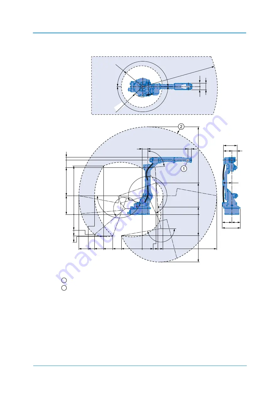
Fig. 6-1: Dimensions and maximum working range of the P-point

P point
Maximum P-point range

All dimensions in mm

1309

580

598

0

540

505

760

200

83

1710

792

559

1041

1284

1287

1284

568

0

199

850

2365

2010

0

374

561

425

150

1082

100

105

q

155

q

170

q

220

q

366

227 139

262

229

491

255

160

q

180

q

R285

86

q

R2010

180

q

83.5

177

93.5

R561

1
2

Summary of Contents for YYR-1-06VXH25-A10

Page 1: ...ROBOTICS YYR 1 06VXH25 A10 GP25 12 Standard Operating and Maintenance Manual...

Page 2: ...ularly and any necessary corrections will be made in subsequent editions Subject to technical modifications Created on 2018 10 Revision 05 Document number E1101000254GB05 Author WOE Modifications made...

Page 3: ...tion 18 4 1 Protection measures 18 4 2 Ambient conditions and installation location 19 4 3 Installation example 20 4 4 Notes on dust proof water poof specifications 24 5 Wiring 25 5 1 Grounding 25 5 2...

Page 4: ...44 9 Maintenance and inspection 47 9 1 Inspection schedule 48 9 2 Note on battery unit 52 9 2 1 Battery pack replacement 52 9 2 2 Multiple connection 55 9 3 Wrist unit 56 9 4 Home position check 57 9...

Page 5: ...NG Indicating possible medium risk hazard situation which can cause death or serious bodily injuries if it is not avoided CAUTION Indicating potentially dangerous situation with low risk of minor or m...

Page 6: ...5XX01 and higher Upgrade procedure manual E1102000223XX01 and higher Installation and wiring E1102000216XX01 or higher Alarm list E1102000217XX01 or higher General operators manual E1102000220XX01 or...

Page 7: ...branch office 1 5 Intended use Typical applications Flange mounting tools Installation of spot welding guns Installation of arc welding equipment Installation of grippers Machining and transporting wo...

Page 8: ...of the robot controller Instructions E1102000214XX01 and higher and Maintenance E1102000215XX01 and higher In order to illustrate details clearly some drawings are shown with the protective covers or...

Page 9: ...ot working Before operating the robot check the function of the EMERGENCY STOP button The servo power must go off immediately when the EMERGENCY STOP button is pressed on the programming pendant see W...

Page 10: ...on yourself in front of the robot whenever possible Always follow the prescribed operating steps see the instructions for the robot controller as well as the Handling and Universal Application manuals...

Page 11: ...nufacturer Address YASKAWA ELECTRIC CORPORATION 2 1 KUROSAKISHIROISHI YAHATANISHI KU KITAKYUSHU JAPAN 1 10 Authorized representative Address YASKAWA Europe GmbH Robotics Division Yaskawastr 1 85391 Al...

Page 12: ...ng the scope of delivery The standard delivery includes the following items Scope of delivery Programming pendant Robot controller Robot Cable The present assembly instruc tions 1 READ ONLY MEMORY REA...

Page 13: ...serial numbers do not match the information on the delivery note Verify whether the serial number of the robot the robot controller and the programming pendant with the delivery The serial number can...

Page 14: ...exerted on the robot or the motors Check that the eyebolts are securely fastened The robot weights approximately 260 kg Use load carrying devices strong enough to withstand the weight The transport sa...

Page 15: ...t Make sure that the robot is lifted as shown in the diagram Transport by crane Transport with crane Wire rope at least 1200 mm long Shipping brackets and bolts 2 screws M12 x 30 2 washers M12 and 2 s...

Page 16: ...should be fixed on a pallet with transport securing devices and shipping bolts Make sure that the forklift and the transportation route have sufficient bearing capacity Always take due care when tran...

Page 17: ...bolts are painted yellow The shipping bracket will be fastened by 2 screws M12 3 3 Damping material during transportation To protect the robots machinery from external forces during transportation sh...

Page 18: ...protective measures can lead to death of people serious bodily harm or material damage Implement the following protection measures Separating protection devices Non contact protection devices Enclosu...

Page 19: ...No water oil or dust and free from excessive electrical noise plasma Free from excessive vibration Vibration acceleration 4 9 m s 0 5 G or less Maximum unevenness of the support surface of the robot b...

Page 20: ...the screws M16 strength class 12 9 Minimum length 50 mm 3 Next fix the robot base to the base plate Tighten the hexagon head bolts and anchor bolts securely so that they will not work loose during ope...

Page 21: ...ted or dry 0 20 Surface black or phosphatized dry 0 10 0 15 0 20 M10 8 8 40 50 60 10 9 59 73 87 12 9 69 84 100 M16 8 8 110 135 160 165 200 235 12 9 190 235 275 M20 8 8 225 275 320 10 9 325 395 470 12...

Page 22: ...s and torques of the robot Direction of move ment Horizontal Vertical Force FH Moment MH Force FV Torque MV Emergency stop Stop category 0 8829 N 6700 Nm 11282 N 13734 Nm Acceleration Decelera tion St...

Page 23: ...pter Alterable Operating Range Precaution against falling In case of suspended mounting take measures to prevent the robot from falling down NOTICE If the setup is changed please contact the local YAS...

Page 24: ...equipments IP 4 Protection from sprays and splashing of water in all directions However the following precautions must be observed Do not use the following liquids because the rubber parts of the rob...

Page 25: ...ndards and wiring regulations for earthing The cable cross section must be 6 mm or more With regard to the direct connection of the earthing cable see figure Earthing connection NOTICE Note on the ear...

Page 26: ...able check the marking on the robot cable and the connections on the connector plate of the robot see the following diagram Robot cable Connect these cable to the robot base connectors and to the robo...

Page 27: ...obot Make sure that you hear each locking clip snap into place clicking sound Fig 5 2 Overhead view of robot cable connection robot side Fig 5 3 Terminal strip of the robot Outside diameter Minimum be...

Page 28: ...roller Make sure that you hear the locking clips snap into place clicking sound Fig 5 4 Connection robot controller 5 2 3 Connecting the programming pendant Connect the programming pendant cable to th...

Page 29: ...on class IP Main axes 54 Wrist axes 67 Maximum speed S axis 3 67 rad s 210 s L axis 3 67 rad s 210 s U axis 3 84 rad s 265 s R axis 7 59 rad s 420 s B axis 7 59 rad s 420 s T axis 12 20 rad s 885 s Al...

Page 30: ...se dimension Parts and work axis label Wrist Wrist unit Robot base Rotary head of the S axis Lower arm L arm Upper arm U arm Robot base dimensions 1 T R B U L R U B T L S S 2 3 4 5 6 316 292 170 0 1 2...

Page 31: ...nge of the P point P point Maximum P point range All dimensions in mm 1309 580 598 0 540 505 760 200 83 1710 792 559 1041 1284 1287 1284 568 0 199 850 2365 2010 0 374 561 425 150 1082 100 1 0 5 q 1 5...

Page 32: ...x 25 screws Strength category 12 9 Tighten the screws with a tightening torque of 206 Nm With a working area of 180 the stop must be mounted as shown in the figure Components of the S axis limit The s...

Page 33: ...ing components are required see the following figure Fig 6 2 Components of the S axis limitation 10 x M16 mounting positions Screws M16 x 25 2 washers M16 Tightening torque 206 Nm S axis working range...

Page 34: ...TOR S MANUAL chapter Softlimit setting function Document No E1102000220XX01 or higher With programming pendant input the numeric value as shown in the following table to modify the parameter Fig 6 3 A...

Page 35: ...The actual overrun distances and overrun times may differ due to internal and external influence on the braking torque According to the mode robot application and number of triggered safety stops wit...

Page 36: ...6 6 5 1 Stop category 0 Measurement condition by category 0 Maximum load Maximum speed Posture of maximum inertia Axis Overrun distance degrees Overrun time second S axis 20 6 0 292 L axis 8 7 0 153 U...

Page 37: ...ction 0 0 0 1 0 2 0 3 0 4 0 5 0 6 0 7 0 8 0 50 100 150 200 250 0 10 20 30 40 50 60 70 0 50 100 150 200 250 0 0 0 1 0 2 0 3 0 4 0 5 0 6 0 7 0 8 0 50 100 150 200 250 0 10 20 30 40 50 60 70 0 50 100 150...

Page 38: ...20 30 40 50 60 70 80 0 50 100 150 200 250 0 0 0 1 0 2 0 3 0 4 0 5 0 6 0 7 0 50 100 150 200 250 0 10 20 30 40 50 60 70 80 0 50 100 150 200 250 0 0 0 1 0 2 0 3 0 4 0 5 0 6 0 7 0 50 100 150 200 250 0 10...

Page 39: ...Technical data 6 39 6 5 2 3 Stop position U axis 100 deflection 0 10 20 30 40 50 60 0 50 100 150 200 250 0 0 0 1 0 2 0 3 0 4 0 5 0 6 0 50 100 150 200 250...

Page 40: ...mounting a tool remove anticorrosive coating on the flange Thinner or light fuel oil are the most suitable for this purpose 7 2 Maximum load of the S axis For peripheral devices of specific applicati...

Page 41: ...ue of the allowable inertia above is calculated assuming that the moment load is at the maximum Thus in the case when only the inertia load is applied when the moment load is small while the inertia l...

Page 42: ...e or attach any other things by using these tightening bolts Do not make any additional holes or tapped holes on the robots body When a load is applied on the upper arm or the rotary head the load set...

Page 43: ...d holes 2 M5 x 10 threaded holes 4 M6 x 12 threaded holes 8 M5 through tap Center of gravity of accessories mount on U arm in this range 4 M10 x 18 threaded holes 4 M6 x 14 threaded holes 4 M10 x 12 t...

Page 44: ...performed by the user The following requirements must be met The total current value for the internal wiring harness must be 40 A The current carrying capacity per single conductor cross section 0 20...

Page 45: ...Straight type and Elbow type Straight type The appearance of the robot with the connector installed is shown in figure Mating connector for internal user I O wiring harness straight type When the con...

Page 46: ...ed the direction shown in the following figure is recommended for the connector installation When assembling the connector the key must be located at the position shown in the following figure Mating...

Page 47: ...ing maintenance and inspection measures Turn OFF the main power supply Put up the required warning sign e g Do not turn the power on Install a switch on guard as prescribed If you have any questions r...

Page 48: ...NOTICE The inspection intervals depend on the SERVO power time see point 1 in The table Inspection intervals applies to normal cases Deviations are to be determined by the TCS service department of Y...

Page 49: ...ws replace if necessary 5 Fixing screws of the cover Using a correspond ing tool tighten loose screws replace if necessary 6 Power input module Manually Check for loose connections 7 Toothed belt for...

Page 50: ...correspond to the following diagram Inspection intervals 2 When checking for conduction with multimeter connect the battery to BAT and OBT of connectors on the motor side for each axis Now remove the...

Page 51: ...Maintenance and inspection 9 51 Fig 9 2 Inspection intervals...

Page 52: ...attery pack 5 After placing the new battery pack into the protective tube fix it with the cable tie T18L 6 Tighten the cover mounting bolts by using the tightening torque shown in figure Location of t...

Page 53: ...nd mount the new battery pack 7 Remove the lead for battery replacement and the battery pack for backup from the multi port connector connect the connector which has been removed in no 3 of this proce...

Page 54: ...s M4 x 12 Tightening torque 2 8 Nm Protective tube 13 screws M4 x 12 Tightening torque 2 8 Nm Battery unit for U and R axes Battery unit for B and T axes Multi port connector board 10 screws M6 x 15 T...

Page 55: ...Absolute encoder data are lost if you remove the plug between engine and multi port connector during battery replacement Do not disconnect the connection between motor and the multi port connector Mu...

Page 56: ...Maintenance and inspection 9 56 9 3 Wrist unit Sealing part U arm Cover Gasket U arm 1 2 3...

Page 57: ...nment mark check below With those alignment marks check for home position deviation on regular basis When home position is disappeared or deviated contact YASKAWA representative Alignment mark check S...

Page 58: ...ck for seeped oil and or oil spot periodically Especially the parts indicated in figure Inspection parts for seeped oil check must be inspected carefully Wipe off seeped oil or oil spot with a cloth b...

Page 59: ...o the ground must be removed to check the hole Move the robot to make the either one of screws marked with face to the ground and remove it to check the hole Positions of grease leakage detection hole...

Page 60: ...ose etc to the grease outlet If this instruction is not followed the motor will be damaged Avoid air getting into the gear Insert grease with a grease gun If an automatic lubricating pump is used the...

Page 61: ...ipe away excess grease with a cloth 6 Remove the lubricating nipple from the grease inlet opening and mount the plug again Before mounting the plug apply to thread part Designation Tightening torque N...

Page 62: ...the main axes Figure the axes S axis gear1 1 In ceiling mounted robots the grease outlet and the grease inlet are located the other way around L axis gear1 U axis gear1 Grease inlet opening Grease ou...

Page 63: ...s Figure the axes R axis gear1 1 In ceiling mounted robots the grease outlet and the grease inlet are located the other way around R axis pinion1 B axis gear1 T axis pinion1 Grease inlet opening Greas...

Page 64: ...ry unit in robot HW1483880 A 186742 Battery unit in robot controller ER6BD_WK77P 3 6V 186743 Line for battery replacement HW1471281 A 186744 Wrist HW1172936 A 186822 Cable harness in robot HW1173052 A...

Page 65: ...Recommended spare parts list 10 65 Connection cable Motor HW1372597 F 191620 Part List robot Designation Type Material no...

Page 66: ...aft seal on the gear TC52647 174066 Shaft sealing housing TC1151306 186834 B axis Gear HW1382522 A 164749 Motor SGM7J 01APK YR1 186765 O ring Motor S30 194291 Gasket cover B motor HW1407822 1 194293 P...

Page 67: ...actor Unit JZRCR APU0 1 186792 Inverter unit With the SERVO control board CSRA SDCA01AA CSRA SDA01H01A 186794 Programming pendant 8 m cable JZRCR APP01 1 183100 DC24V fuse for I O 02173 15P 3 15A 250V...

Page 68: ...3 B Gear 1 1005 M8 25 Screw 3 1006 M4 6 Screw 4 1001 1002 1003 1004 1011 1019 1020 1030 1027 1017 1018 1028 1029 1053 1054 1055 1056 1057 1058 1050 1049 1051 1052 1047 1048 1032 1031 1034 1033 1026 10...

Page 69: ...3 PMF8 03 Union 1 1024 NPT3 8 Sealing plug 2 1025 KQ2L08 00 Union 1 1026 NB 0860 0 24 Tube 1 1027 M5 10 Screw 6 1028 HW1304382 1 Cover 1 1029 M6 15 Screw 2 1030 HW1405970 2 Bush 1 1031 HW1408196 1 Cov...

Page 70: ...49 CD31 Saddle 1 1050 M5 8 Screw 2 1051 TA1 S10 Clamp 1 1052 M5 8 Screw 1 1053 HW1405589 1 Support 1 1054 M5 12 Screw 2 1055 CD39 Saddle 1 1056 M5 8 Screw 2 1057 TA1 S10 Clamp 1 1058 M5 8 Screw 1 1059...

Page 71: ...1 4001 4002 4003 4004 4005 4007 4008 4009 4010 4012 4014 4016 4017 4018 4020 4021 4022 4025 4023 4024 4026 4027 4024 4028 4028 4029 4034 4030 4032 4033 4031 4035 4036 4037 4038 4039 4040 4042 4041 404...

Page 72: ...Housing 1 4021 HW1304319 1 Gear set Gear 1 1 4022 HW1304320 2 Gear set Gear 2 1 4023 M4 14 Screw 1 4024 2L 4 Washer 1 4025 M3 12 Screw 4 4026 M4 12 Screw 4 4027 M4 12 Screw 4 4028 PT1 8 Sealing plug...

Page 73: ...erminal A 2 5 Terminal 1 4053 M4 12 Screw 1 4054 HW1307283 1 Shaft 1 4055 HW1200682 1 Spacer block 1 4056 M6 x 20 Screw 8 4057 2L 6 Washer 8 4058 M6 x 25 Screw 6 4059 2L 6 Washer 6 4060 HW1409083 1 Su...

Page 74: ...5014 5057 5070 5057 5002 5004 5006 5044 5063 5039 5071 5069 5064 5034 5005 5048 5043 5045 5033 5058 5058 5058 5020 5031 5042 5008 5032 5027 5026 5058 5058 5036 5010 5035 5009 5053 5054 5030 5059 5016...

Page 75: ...W1404047 1 Housing 1 5019 HW1407204 1 B Support 1 5020 HW1404049 1 Cover 1 5021 HW1407617 1 M Base 1 5022 HW1407823 1 Sealing 1 5023 S30 O ring 1 5024 HW1407246 1 Flywheel 1 5025 HW1407202 1 Shaft 1 5...

Page 76: ...5056 2L 8 Washer 1 5057 M3 x 28 Screw 18 5058 M3 x 10 Screw 39 5059 M4 x 12 Screw 4 5060 M3 x 20 Screw 12 5061 M3 x 16 Screw 4 5062 M4 x 10 Screw 2 5063 M4 x 12 Screw 4 5064 M6 x 6 Screw 5 5065 M4 x 1...

Page 77: ...Parts lists 11 77...

Page 78: ...yin 972 3 9004114 NL YASKAWA Benelux B V Son 31 40 2895500 PL YASKAWA Polska Sp z o o Wroc aw 48 71 7928670 RUS YASKAWA Nordic AB Moskva 46 480 417 800 SE YASKAWA Nordic AB Tors s 46 480 417 800 SI YA...

Reviews: