10
GB
O R I G I N A L I N S T R U C T I O N S
CHARACTERISTIC OF THE TOOL
The pneumatic eccentric grinder is a tool which uses compressed air under appropriate pressure to operate. The grinding blade
is equipped with a Velcro-type fastener that allows the attachment of paper or abrasive cloth discs of diff erent grain sizes and
applications. The grinder is mainly used in painting works related to preparation of surfaces for subsequent stages of varnishing.
Proper, reliable and safe operation of the tool depends on appropriate use, that is why you should:
read and keep the entire instruction manual before the fi rst use of the tool.
The supplier shall not be held liable for any damage or injury resulting from improper use of the tool, failure to observe the safety
regulations and recommendations of this manual. Use of the tool for purposes other than those for which it was intended shall
cause the loss of the user’s rights to the warranty, as well as under inconsistencies with the agreement.
ACCESSORIES
The grinder is equipped with a connector to connect to the pneumatic system. The grinder is fi tted with 150 mm diameter wheel.
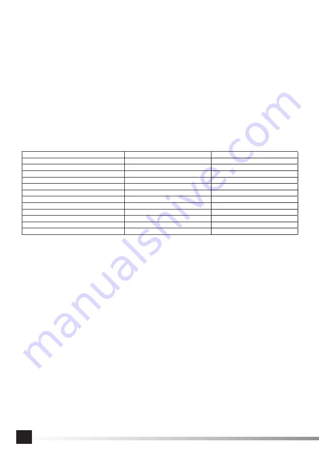
TECHNICAL DATA
Parameter
Unit
Value
Catalog number
YT-09739
Weight
[kg]
0,95
The diameter of air connection (PT)
[mm]
6,3 / 1/4
The diameter of air supply hose (internal)
[” / mm]
10 / 3/8
Revs
[min
-1
]
12 000
The diameter of tool handle
[mm]
M8
Diameter of the disk
[mm]
150
Maximum operation pressure
[MPa]
0,63
Required air fl ow (at 6.2 bar)
[l/min]
84
Acustic pressure (EN ISO 15744)
[dB(A)]
90 ± 3
Acustic power (EN ISO 15744)
[dB(A)]
101 ± 3
Vibrations (ISO 28927-3)
[m/s
2
]
4,4 ± 2,5
GENERAL SAFETY CONDITIONS
WARNING! During the tool operation you should always adhere to the fundamental principles of security including the following
guidelines, in order to reduce the risk of fi re, electric shock, and avoid injuries.
Before proceeding to the use of this tool you should read the whole instruction and keep it.
ATTENTION! Read all the following guidelines. Failure to comply with them may lead to electric shock, fi re, or damage to the
body. The concept of a
“pneumatic tool
”, which is used in the instructions refers to all tools driven by compressed air stream under
proper pressure.
FOLLOW THE GUIDELINES BELOW
General safety rules
Prior to installation, operation, repair, maintenance and modifi cation of accessories or, in the case of work near pneumatic tool,
because of the many risks, you should read and understand the safety instructions. Lack of implementation of these activities
can result in serious injury. Installation, regulation and assembly of pneumatic tools can be performed only by qualifi ed and
trained personnel. Do not modify the pneumatic tool. Modifi cations may reduce its effi ciency and safety level and increase the
risk for the tool operator. Do not throw away the safety instructions, they must be passed to the tool operator. Do not use the
pneumatic tool, if it is damaged. The tool should be periodically inspected for visibility of data, which is required by the standard
ISO 11148. The employer / user should contact the manufacturer in order to exchange plate every time when it is necessary.
The risks associated with entanglement
The risks associated with entanglement may cause choking, scalping and / or injury when loose clothing, jewelry, hair or gloves
are not kept away from tool and accessories.
The risks associated with work
The use of tool can put hands operator risks, such as: crushing, impact, cutting, abrasion and heat. You should wear appro-
priate gloves to protect your hands. The operator and maintenance staff should be able to cope physically with the quantity,
Summary of Contents for YT-09739
Page 21: ...21 RUS...
Page 22: ...22 RUS II...
Page 23: ...23 RUS IV V SAE 10 10 3 8 1 38 VI...
Page 24: ...24 RUS WD 40 30 SAE 10 SAE 10 WD 40 6 100 WD 40 30 10 3 8 0 3 MPa...
Page 26: ...26 UA 10...
Page 27: ...27 UA...
Page 28: ...28 UA II IV V SAE 10 10 3 8 1 38 VI...
Page 29: ...29 UA WD 40 30 SAE 10 SAE 10 WD 40 6 100 WD 40 30 10 3 8 0 3 MPa...
Page 80: ...80 GR...
Page 81: ...81 GR...
Page 82: ...82 GR IV V SAE 10 10 mm 3 8 1 38 MPa V VI...
Page 83: ...83 GR 0 WD 40 30 SAE 10 SAE 10 WD 40 6 100...


