13
PL
GB
O P E R A T I N G M A N U A L
Measurement of intensity of the current
Depending on the expected value of the measured intensity of the current connect the measurement cables to the socket marked
as „
μ
A/mA” and „COM” or to the socket marked as „10A” and „COM”. Use the selector to choose the adequate measurement range
and the „Select” button to choose the kind of the measured current. Maximum intensity of the current measured through the socket
marked as „
μ
A/mA” may amount to 600 mA, and in case it is higher than 600 mA, the cable must be connected to the „10A” socket.
The duration of the measurements of currents exceeding 2 A must not exceed 10 seconds, and it is required to wait at least 15 minutes
before the next measurement.
The maximum current and voltage values of the sockets must not be exceeded.
Connect the
measurement cables in series to the tested electric circuit, select the range and kind of the current and read the result of the measure-
ment. The first stage of the measurements is to select the maximum measurement range. In order to ensure more precise results of
the measurement you may change the measurement range.
Measurements of resistance
Connect the measurement cables to the sockets marked as „V
Ω
Hz” and „COM”; switch the range selector to the position of the meas-
urement of resistance. Place the measurements leads at the terminals of the measured element and read the result. In order to ensure
more precise results of the measurement the measurement range may be changed if required.
It is strictly prohibited to measure
the resistance of live elements.
In case of measurements of values exceeding 1M
Ω
the measurement may take a couple of seconds
before the result is stable, which is a normal reaction during measurements of high resistances.
Before the measurements leads are placed at the element to be measured, the „OL” symbol is displayed.
Measurement of capacitance
Connect the measurement cables to the sockets marked as „V
Ω
Hz” and „COM”; switch the range selector to the position of the meas-
urement of capacitance. Make sure the capacitor was discharged before the measurement.
Do not ever measure the capacitance
of a charged capacitor, since it might damage the meter and cause an electric shock.
Push the „Rel/USB” button, after which
a triangle will be displayed indicating a relative value measurement. It will permit to reduce the influence of measurement cables ca-
pacitance upon the result of the measurement. In case of measurements of high-capacitance condensers the measurement may last
approximately 30 seconds before the result is stable. In case of measurements of capacities amounting to 4000
μ
F or higher, the „OL”
will be displayed. The maximum result of the capacitance measurements that may be displayed is „3999”.
Measurements of frequency
Connect the measurement cables to the sockets marked as „V
Ω
Hz” and „COM”; switch the range selector to the „Hz/Duty” position.
Use the „Select” button to choose measurements of frequency, after which „Hz” will be displayed. Read the result of the measurement
in the display. In case of measurements of frequency, the voltage of the measured signal should be between 1 V rms and 20 V rms. In
case of measurements of a signal whose voltage exceeds 20 V rms, the precision of the measurement exceeds the range indicated
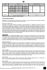
in the table.
Diode test
Connect the measurement cables to the sockets marked as „V
Ω
Hz” and „COM”, and switch the selector to the diode symbol. Use the
„Select” button select diode test, after which the diode symbol will be displayed. Place the measurement leads at the diode terminals
in the conduction direction and the reverse direction. If the diode is functioning correctly, then at the diode connected in the forward
direction we will read the voltage drop for this diode expressed in V. In case the diode is connected in the reverse direction the display
will read „OL. Correctly functioning diodes show a low resistance in the forward direction and a high resistance in the reverse direction.
It is strictly prohibited to test live diodes.
Conduction test
Connect the measurement cables to the sockets marked as „V
Ω
Hz” and „COM”. Use the „Select” button to select conduction test. The
buzzer symbol will be displayed. In case the meter is used for conduction measurements, the internal buzzer will emit sound each time
the measured resistance drops below 20
Ω
. Above 150
Ω
the buzzer will not sound.
It is strictly prohibited to test the conduction
of live circuits.
Measurement of temperature
Connect the thermoelement leads to the sockets marked as „
μ
A/mA” and „COM”. Switch the selector of the meter to „TEMP”. Put the
thermoelement to the measured object. The thermoelement supplied with the device permits to realise measurements only up to 250
O
C. In order to measure higher temperatures it is necessary to purchase a thermoelement that permits to measure higher tempera-
tures. It is required to use thermoelements type K.
Measurement of the pulse-duty factor
Connect the measurement cables to the sockets marked as „V
Ω
Hz” and „COM”. Switch the selector of the meter to „Hz/Duty” Use
the „Hz/Duty” button to select the measurement of the pulse-duty factor. The symbol „%” will be displayed. Read the result of the
measurement in the display. The voltage of the measured signal should be between 4 Vp-p and 10 Vp-p, and the frequency of the
signal should be between 4Hz and 1kHz. If the parameters of the measured signal exceed the indicated range, the precision exceeds
the range indicated in the table.
Vp-p – voltage between the peak points of the signal.


