background image

12

GB

O R I G I N A L   I N S T R U C T I O N S

of cooling the tool. Do not cool the welder submerging it in water, which may lead to electric shock. 

Do not install more than one set of adapters. This will reduce the risk of burns. Adapters may be replaced only once they have 

cooled down completely. While replacing adapters, it is required to disconnect the power supply cord of the welder from the mains 

socket. Before work may commence, make sure the adapters are tightly installed on the heating head. 

The welding operation must not be repeated using the same connecting element, since this might expose the active parts.

This appliance can be used by children aged from 8 years and above and persons with reduced physical, sensory or mental ca-

pabilities or lack of experience and knowledge if they have been given supervision or instruction concerning use of the appliance 

in a safe way and understand the hazards involved. Children shall not play with the appliance. Cleaning and user maintenance 

shall not be made by children without supervision.

USING THE TOOL

Before work make sure the housing, the connection cord with the plug and the external extension cords are not damaged. If 

necessary clean the tool and the ventilation slots. Do not clean the welder with metal tools which might damage the surface of the 

connection elements or the heating head. In case any damage is detected, it is prohibited to continue work!

Attention! 

Any actions related to replacing pipe adapters, cleaning etc. must be carried out while the tool is off, so before such 

actions: 

Remove the plug of the tool from the mains socket!

Installation of pipe adapters (II)

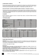
Select the set of adapters corresponding to a single diameter. Make sure the contact surface between the heating head and the 

adapters is not dirty. Screw the adapters tightly at both sides of the heating head. The place of installation of the adapters to the 

heating head must be selected complying with the rule that smaller adapters must be installed closer to the end of the head. The 

edge of the adapter must not protrude beyond the limit of the heating head. 

Only one diameter of adapters may be installed at one time. 
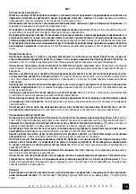
Heating

Once the installation has been finished, place the welder on the support (III). Make sure the pipe adapters and the heating head 

are not in contact with other objects. Connect the plug of the power supply cord to the mains.

The display will show the current temperature of the heating element. 

Once the „MODE” button has been pressed, the temperature adjustment mode is selected. The temperature may be adjusted with 

the „UP” and „DOWN” arrows, adequately increasing or reducing the displayed value. It is possible to adjust the whole number of 

grades or each digit separately, which permits quicker adjustments of the required value. Switching between the digits is realised 

with the „LEFT” arrow. The digit which is being adjusted is pulsating. 

Once the temperature has been adjusted, press again the „MODE” button. This will start the heating process signalled by a pulsat-

ing „OUT” light. The increase of the current temperature may be observed in the display. 

If the „OUT” light stops pulsating while the „ALM” light is on, the set temperature has been reached. The welder is ready for work.

ATTENTION!

 At the end of the heating process the „ALM” light goes on while the „OUT” light is pulsating, which indicates a close 

end of the heating process.

ATTENTION!

 During work the „OUT” light may be pulsating periodically, which indicates heating of the head. 

ATTENTION!

 The display may indicate a slightly different temperature than the value set by the user. This is a normal effect 

related to thermal inertia.
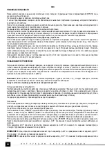
Welding

The elements to be welded must be cleaned of any dirt, humidity and dust.

Once the heating process has concluded place a pipe or connecting element on the adapter (V). Place one part on the adapter 

and the other one in the adapter so that there is a slight difference of the diameter of the elements being welded. 

Leave the elements on the adapter for the time indicated in the table. Then the welded elements must be removed from the adapt-

ers and connected by inserting them into each other. Do not insert the elements deeper than the limit of the heated area. Leave 

the connection to cool down, avoiding any deformation.

Once the work has concluded turn the welder off disconnecting the plug from the mains. Place the welder on the support until it has 

cooled down completely. Disassemble the pipe adapters and carry out maintenance actions of the tool and the adapters.

MAINTENANCE AND OVERHAUL

ATTENTION! Before any adjustment, technical service or maintenance operations unplug the tool. Once the operations have been 

finished, the technical conditions of the tool must be assessed by means of external evaluation and inspection of the following 

elements: body and handle, conductor with a plug and deflection, functioning of the electric switch, patency of ventilation slots, 

sparking of brushes, noise level of functioning of bearings and gears, start-up and smoothness of operation. During the guarantee 

period, the user cannot dismantle the electric tools or change any sub-assemblies or elements, since it will cancel any guarantee 

Summary of Contents for YT-82250

Page 1: ...LASTISCHE ROHRE TERMOPLASTINI VAMZD I SUVIRINIMO APARATAS METIN ANAS APAR TS TERMOPLASTISK M CAURUL M SV E KA NA TERMOPLASTICK TRUBKY ZV RA KA NA TERMOPLASTOV R RY HEGESZT BERENDEZ S TERMOPLASZTIKUS C...

Page 2: ...ear Produktionsjahr Pagaminimo metai 2016 Ra o anas gads Rok v roby Rok v roby Gy rt si v Anul produc iei utilajului A o de fabricaci n TOYA S A ul So tysowicka 13 15 51 168 Wroc aw Polska PL GB D RUS...

Page 3: ...IM 9 tla idlo V AVO 10 tla idlo NAHOR 11 tla idlo NADOL 12 kontrolka ALM 13 kontrolka OUT 1 h z 2 foganty 3 hegeszt fej 4 h l zati k bel 5 cs adapter 6 talp 7 kijelz 8 ZEMM D nyom gomb 9 BALRA nyom go...

Page 4: ...Nennfrequenz tampa ir nominalus da nis Nomin ls spriegums un nomin la frekvence Jmenovit nap t a frekvence Menovit nap tie a frekvencia N vleges fesz lts g s frekvencia Tensiunea i frecven a nominal T...

Page 5: ...kazuje na nutnos separovan ho zberu opotrebovan ch elektrick ch a elektronick ch zariaden Opotrebovan elektrick zariadenia s zdrojom druhotn ch surov n je zak zan vyhadzova ich do kontejnerov na komun...

Page 6: ...wierzchni adapter w do rur O C 0 300 Masa kg 1 3 Zakres temperatury pracy O C 0 40 Klasa izolacji elektrycznej I Stopie ochrony IPX0 Tabela nagrzewania w zale no ci od rednicy rur rednica rury Czas na...

Page 7: ...iem elektrycznym w przypadku niespodziewanych sytuacji podczas pracy Stosuj odzie ochronn Nie zak adaj lu niej odzie y i bi uterii Utrzymuj w osy odzie i r kawice robocze z dala od rucho mych cz ci na...

Page 8: ...rzed przyst pieniem do tych czynno ci Wyci gn wtyczk przewodu narz dzia z gniazda sieciowego Monta adapter w do rur II Nale y wybra zestaw adapter w odpowiadaj cych jednej rednicy Upewni si e powierzc...

Page 9: ...ci przewodu elektrycznego z wtyczk i odgi tk dzia ania w cznika elektrycznego dro no ci szczelin wentyla cyjnych iskrzenia szczotek g o no ci pracy o ysk i przek adni rozruchu i r wnomierno ci pracy...

Page 10: ...lass I Protection grade IPX4 Welding parameters table in accordance with the pipe diameter Pipe diameter Heating time approximate Depth of pipe heating Cooling time for bonds mm s mm min 16 8 12 3 20...

Page 11: ...Do not overload the electric tool Use a proper tool for the given purpose A correct selection of the tool for the given work will result in a more efficient and safer work Do not use the electric tool...

Page 12: ...n pressed the temperature adjustment mode is selected The temperature may be adjusted with the UP and DOWN arrows adequately increasing or reducing the displayed value It is possible to adjust the who...

Page 13: ...he tool repaired at a service shop Once the functioning has been concluded the casing ventilation slots switches additional handle and protections must be cleansed with a stream of air at a pressure n...

Page 14: ...der Rohradapter O C 0 300 Gewicht kg 1 3 Betriebstemperaturbereich O C 0 40 Klasse der elektrischen Isolation I Schutzgrad IPX0 Tabelle f r das Anw rmen in Abh ngigkeit vom Durchmesser der Rohre Rohrd...

Page 15: ...kann ernsthafte K rperver letzungen herbeif hren Gleichgewicht halten Durch die ganze Zeit entsprechende Arbeitsstellung einnehmen Dadurch l sst sich das Elektrowerk zeug in den unerwarteten Notf llen...

Page 16: ...che der Verbin dungselemente oder des Heizkopfes zerst ren oder besch digen k nnten Werden Besch digungen festgestellt ist ein weiterer Funktionsbetrieb verboten Achtung Alle T tigkeiten im Zusammenha...

Page 17: ...leibt bis zum v lligen Abk hlen auf dem Untergestell Danach sind die Rohr adapter zu demontieren und das Ger t wie auch die Adapter werden Wartungsarbeiten unterzogen KONSERVIERUNG UND BERSICHTUNGEN A...

Page 18: ...18 RUS YT 82250 V 230 Hz 50 W 850 O C 0 300 kg 1 3 O C 0 40 I IPX0 mm s mm min 16 8 12 3 20 10 14 3 25 14 16 3 32 16 20 4 40 24 21 4 50 36 22 5 5 63 48 24 6 0 5O C 50...

Page 19: ...19 RUS...

Page 20: ...20 RUS 230V 50Hz II III OUT OUT ALM ALM OUT OUT...

Page 21: ...21 RUS V 0 3 MPa...

Page 22: ...22 UA YT 82250 V 230 Hz 50 W 850 O C 0 300 kg 1 3 O C 0 40 I IPX0 mm s mm min 16 8 12 3 20 10 14 3 25 14 16 3 32 16 20 4 40 24 21 4 50 36 22 5 5 63 48 24 6 0 5O C 50...

Page 23: ...23 UA...

Page 24: ...24 UA 230V 50Hz II III OUT OUT ALM ALM OUT OUT...

Page 25: ...25 UA V 0 3 MPa...

Page 26: ...O C 0 40 Elektros izoliacijos klas I Apsaugos laipsnis IPX0 Priklausomo nuo vamzd i diametro ildymo lentel Vamzd io diametras ildymo laikas Vamzd io ildymo gylis Sujungimo au imo laikas mm s mm min 1...

Page 27: ...li nuo judam elektrinio rankio dali Laisvi drabu iai juvelyriniai dirbiniai arba ilgi plaukai gali sivelti judamas rankio dalis Vartok dulki siurbimo priemones arba dulki kaupimo rezervuarus jeigu ran...

Page 28: ...galvut s galo Vamzd i jungikli kra tas negali i siki ti u ildymo galvut s rib Galima vienu kartu montuoti tik vieno diametro vamzd i jungiklius Kaitinimas U baigus montavim suvirinimo ma in reikia pas...

Page 29: ...iavim guoli ir pavar darbo garsum paleidim ir darbo tolygum Garantijos metu vartotojas negali demontuoti elektros rengini nei keisti bet kokius mazginius surinkimus arba sudedam sias dalis kadangi to...

Page 30: ...anas laiks Caurules sasild anas dzi ums Savienojuma atdz anas laiks mm s mm min 16 8 12 3 20 10 14 3 25 14 16 3 32 16 20 4 40 24 21 4 50 36 22 5 5 63 48 24 6 Gad jum ja darbs ir veikts temperat r s no...

Page 31: ...isko sl dz ju ir b stama un j b t atdota remontam Atsl gt kontaktdak u no ligzdas pirms regul anas aksesu ru main anas un ier ces glab anas Tas var sarg t no ie r ces gad juma iesl g anas Glab t ier c...

Page 32: ...vienlaic gi iesl gto ALM kontrolspuldzi tas noz m ka noteikta temperat ra tika sasniegta Ier ce ir gatava darbam UZMAN BU Uzsild anas procesa beigum s ks sp d t ALM kontrolspuldze ar vienlaic gi puls...

Page 33: ...teplot O C 0 40 T da elektrick izolace I Stupe ochrany IPX0 Tabulka as zah v n v z vislosti na pr m ru trubek Pr m r trubky Doba zah v n Hloubka vyh v n trubky as chladnut spoje mm s mm min 16 8 12 3...

Page 34: ...se mohou zachytit do pohybliv ch st n ad Pou vej ods va e prachu nebo z sobn ky na prach jestli e je n ad t mto zp sobem vybaveno Postarej se o to aby byly spr vn p ipojeny Pou v n ods va e prachu sni...

Page 35: ...dokon en mont e je t eba postavit sv e ku na stojan III Zkontrolujte zda se adapt ry na trubky a vyh vac hlava nedo t kaj jin ch p edm t Z str ku p vodn ho kabelu p ipojte do z suvky elektrick s t Na...

Page 36: ...doby pou ivatel nesmi demontovat elektron ad ani m nit ve kere provozn jednotky nebo sou sti proto e m e stratit narok na z ruku Ve kere nespravnosti zji t ne b hem prohl dky nebo provozov n jsou sig...

Page 37: ...ov na r ry O C 0 300 Hmotnos kg 1 3 Rozsah prev dzkovej teploty O C 0 40 Trieda elektrickej izol cie I Stupe ochrany IPX0 Tabu ka asov nahrievania v z vislosti od priemeru r r Priemer r ry as nahrieva...

Page 38: ...po as pr ce Pou vaj ochrann odev Neobliekaj si vo n odev nenos bi ut riu Udr uj vlasy odev a pracovn rukavice v dostato nej vzdialenosti od pohybliv ch ast elektrick ho n radia Vo n odev bi ut ria al...

Page 39: ...ran ch v hrevnej hlavy Pri mont i adapt rov je potrebn zvoli ich optim lnu polohu vo i hlave pri om je treba sa riadi pravidlom e men ie adapt ry sa montuj bli ie ku koncu hlavy Hrana adapt ra nesmie...

Page 40: ...chodnosti ventila n ch trbin iskrenie kart ov hlasitosti lo isek a p evodovek uv dzania do pohybu a rovnomernosti prace Po as z ru n ho obdobia pou ivate nesmi demontova elektron rad ani meni provozn...

Page 41: ...0 A cs adapterek fel let nek h m rs klete O C 0 300 T meg kg 1 3 zemi h m rs klet O C 0 40 Elektromos szigetel si oszt ly I V delmi fokozat IPX0 Felf t si t bl zat a cs tm r f ggv ny ben Cs tm r Felf...

Page 42: ...lektromos berendez s t l Laza ruh zat kszer illetve hossz haj beleakadhat a berendez s mozg alkatr szeibe Amennyiben lehets ges haszn ljon porelsz v kat illetve port rol kat gyeljen a megfelel szab ly...

Page 43: ...a vonatkoz an hogy az adaptereket hova kell r gz teni a fejre az ir nyad alapelv az hogy a kisebb adaptereket a fej v g hez k zelebb kell felszerelni Az adapter pereme nem ny lhat t l a f t fej sz l n...

Page 44: ...i lis id szakban a felhaszn l nem szerelhet az elektromos berendez shez s nem is cser lhet ki semmif le r szegys get vagy tartoz kot mivel ez a garanci lis jog elveszt s vel j r A szemrev telez sn l v...

Page 45: ...aturii de lucru O C 0 40 Clasa izolacji electrice I Gradul de protejare IPX0 Tabelul nc lzirii care depinde de diametrul evii Diametrul tevii Timp de nc lzire Ad ncimea nc lzirii Timp pentru r cire mm...

Page 46: ...t pozi ie i va permite s st p ne ti scula electric n cazuri de situa ii de lucru nea teptate Impbrac te n haine de protejare Nu te mbr ca n haine largi i cu bijuterii P rul mbr c mintea i m nu ile s n...

Page 47: ...i sigur cu uruburi pe ambele p r i la capul nc lzitor Adapoarele mai mici se monteaz mai aproape de cap tul capului Marginea adaptorului nu poate dep i suprafa a capului nc lzitor Se permite montarea...

Page 48: ...riilor c rbunilor sonoritatea lag relor i angrenajului pornirea i corectitudinea func ion rii In timpul garan iei uzufructuarul nu poate anexa nimic la scula respectiv i nici nu poate s schimbe nici u...

Page 49: ...inal W 850 Temperatura de la superficie de los adaptadores para tubos O C 0 300 Masa kg 1 3 Rango de la temperatura de trabajo O C 0 40 Clase de aislamiento el ctrico I Grado de protecci n IPX0 Tabla...

Page 50: ...rante el trabajo Use ropa protectora No se ponga ropa floja y bisuter a Mantenga el cabello la ropa y los guantes lejos de los elemen tos m viles de la herramienta el ctrica Ropa floja bisuter a o cab...

Page 51: ...al reemplazo de los adaptadores de los tubos etc deben realizarse habiendo apagado la tensi n de la alimentaci n el ctrica de la herramienta y por lo tanto antes de tales operaciones Saque la clavija...

Page 52: ...NTENIMIENTO E INSPECCIONES ATENCI N Antes de empezar el ajuste servicio t cnico o mantenimiento saque el enchufe de la herramienta del contacto de la red el ctrica Habiendo terminado el trabajo es men...

Reviews: