19
CHILLED/HOT WATER PIPING
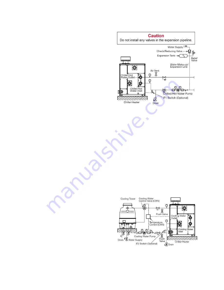
A balance valve should be installed at
the chilled/hot water outlet and a stop
valve
should
be
installed
at
the
chilled/hot water inlet. Both valves
should be placed in close proximity to the
chiller-heater.
After thoroughly testing for leaks,
insulate the piping circuit, ensuring an
adequate vapor barrier is obtained. Be
sure to allow access to any valves, wells,
and ports that may be present. Also,
ensure the chiller-heater panels are not
restricted by the insulation.
Figure 20
– Chilled/Hot Water Piping
COOLING WATER PIPING
Cooling water should be supplied at
85°F
(29.5°C)
or less. The CH-MG Series
can adapt to cooling water down to 65°F
(18.5°C)
without the need of a mixing
valve. However, the inlet cooling water
temperature must not be below 46.4°F
(8°C)
when the cooling cycle starts, nor
may it drop to 46.4°F
(8°C)
and remain
there for more than 3 minutes at any
point in time. Such cases will result in
the generation of error code E043. This
error code will automatically reset itself
once the cooling water warms above
48.2°F
(9°C)
.
To prevent a hot slug of water from
potentially damaging the cooling tower, a
Cooling Water Control Valve
(CWV)
should be used and set so that it
bypasses into the sump of the cooling
tower for the first 2 minutes of the first
cooling cycle after the unit has changed
over from heating mode. This same
valve can also be used to divert water
that is too cold into the sump of the
cooling tower until the water has warmed
up to an acceptable temperature.
Higher temperatures than 85°F
(29.5°C)
can result in a loss of capacity. In some
cases, the burner will simply be able to
ramp up the firing rate to compensate,
but this lowers the efficiency of the unit
and should be avoided. If cooling water
exceeds 90°F
(32°C)
, the refrigerant
vapor may no longer condense properly,
which could lead to a loss of capacity as
well. If the cooling water becomes
consistently too hot, the unit may lock
out.
Figure 21
– Cooling Water Piping
Summary of Contents for AROACE CH-MG150
Page 4: ...4 EQUIPMENT DIMENSIONS Figure 1 MG150 Dimensions ...
Page 5: ...5 EQUIPMENT DIMENSIONS Figure 2 MG200 Dimensions ...
Page 6: ...6 INTERNAL WIRING DIAGRAM ...
Page 7: ...7 ...
Page 8: ...8 Table 2 Internal Wiring Diagram Legend KRCH relay has been replaced by the KCH relay ...
Page 12: ...12 INSTALLATION CLEARANCES Figure 7 Installation and Service Clearances ...


